


Manual 2100-537
I
Page
27 of 54
GROUND WATER
(WELL SYSTEM APPLICATIONS)
NOTE:
Unit shipped from factory with 60 PSIG low pressure
switch wired into control circuit for ground water
applications.
WATER CONNECTIONS
It is very important that an adequate supply of clean, non-
corrosive water at the proper pressure be provided before
the installation is made. Insufficient water, in the heating
mode for example, will cause the low pressure switch to
trip, shutting down the heat pump. In assessing the capacity
of the water system, it is advisable that the complete water
system be evaluated to prevent possible lack of water or
water pressure at various household fixtures whenever the
heat pump turns on. All plumbing to and from the unit is to
be installed in accordance with local plumbing codes. The
use of plastic pipe, where permissible, is recommended to
prevent electrolytic corrosion of the water pipe. Because
of the relatively cold temperatures encountered with well
water, it is strongly recommended that the water lines
connecting the unit be insulated to prevent water droplets
from condensing on the pipe surface.
Refer to piping, Figure 11. Slow open/close with
End
Switch (2)
, 24V, provides on/off control of the water flow to
the unit. Refer to the wiring diagram for correct hookup of
the valve solenoid coil.
Constant Flow Valve (3)
provides correct flow of water to
the unit regardless of variations in water pressure. Observe
the water flow direction indicated by the arrow on the side
of the valve body. Following is a table showing which
valve is to be installed with which heat pump.
Strainer (8)
installed upstream of
water coil inlet
to collect
foreign material which would clog the flow valve orifice.
The figure shows the use of
shutoff valves (4)
and
(5)
, on
the in and out water lines to permit isolation of the unit from
the plumbing system should future service work require this.
Globe valves should not be used as shutoff valves because
of the excessive pressure drop inherent in the valve design.
Instead use gate or ball valves as shutoffs, so as to minimize
pressure drop.
Hose bib (6)
and
(7)
, and tees should be included to permit
acid cleaning the refrigerant-to-water coil should such
cleaning be required. See WATER CORROSION.
Hose bib (1)
provides access to the system to check water
flow through the constant flow valve to insure adequate
water flow through the unit. A water meter is used to check
the water flow rate.
WELL PUMP SIZING
Strictly speaking, sizing the well pump is the responsibility
of the well drilling contractor. It is important, however,
that the HVAC contractor be familiar with the factors that
determine what size pump will be required. Rule of thumb
estimates will invariably lead to under or oversized well
pumps. Undersizing the pump will result in inadequate
water to the whole plumbing system, but with especially bad
results to the heat pump – NO HEAT / NO COOL calls will
result. Oversized pumps will short cycle and could cause
premature pump motor or switch failures.
The well pump must be capable of supplying enough water
and at an adequate pressure to meet competing demands of
water fixtures. The well pump must be sized in such a way
that three requirements are met:
1. Adequate flow rate in GPM.
2. Adequate pressure at the fixture.
3. Able to meet the above from the depth of the
well-feet of lift.
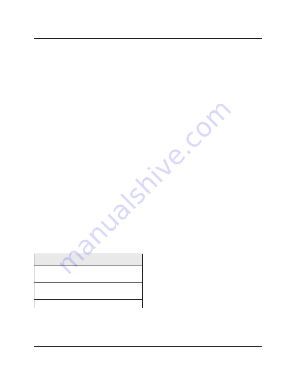
TABLE 8
CONSTANT FLOW VALVES
(1)
The pressure drop through the constant flow valve will
vary depending on the available pressure ahead of the valve.
Unless minimum of 15 psig is available
immediately
ahead
of the valve, no water will flow.
Part No.
Min. Available
Pressure PSIG
Flow Rate
GPM
CFV-5
15 (1)
5
CFV-6
15 (1)
6
CFV-7
15 (1)
7
CFV-9
15 (1)
9
CFV-10
15 (1)
10


