HEX18GARC-KIT
QUICK REFERENCE GUIDE
www.blustream.com.au
|
www.blustream-us.com
|
www.blustream.co.uk
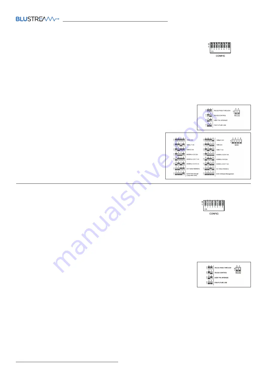
The Transmitter features and 8-pin DIP switch on the front panel.
The switches allow you to configure various functions of the Transmitter as follows:
DIP switch 1:
Specify between 5V IR or 12V IR equipment in use. Blustream IR equipment supplied is 5V. DIP switch
pointing UP for 5V IR equipment. DIP switch pointing DOWN for 12V IR equipment.
DIP switch 2:
This switch allows you to specify between USB Host or USB Device mode. DIP switch pointing UP if the
unit is connected to the HOST. DIP switch pointing DOWN if connected to DEVICES.
DIP switch 3-4:
This switch allows you to select the RS-232 port configuration.
See adjacent image:
DIP switch 5-8:
This switch allows you to specify an EDID to handshake
with the source device. See adjacent image. The EDID Software
Management setting will allow for an EDID setting to be chosen via an
RS-232 API command (see full manual for API commands - download
from the Blustream website).
TX Config Switches
RX Config Switches
The Receiver features and 8-pin DIP switch on the front panel.
The switches allow you to configure various functions of the Receiver as follows:
DIP switch 1:
Specify between 5V IR or 12V IR equipment in use. Blustream IR equipment supplied is 5V. DIP switch
pointing UP for 5V IR equipment. DIP switch pointing DOWN for 12V IR equipment.
DIP switch 2:
This switch allows you to specify between USB Host or USB Device mode. DIP switch pointing UP if the
unit is connected to the HOST. DIP switch pointing DOWN if connected to DEVICES.
DIP switch 3-4:
This switch allows you to select the RS-232 port configuration.
See adjacent image:
DIP switch 5:
This switch allows you to enable or disable bi-directional CEC pass-through from a display device to a
source device. DIP switch pointing UP for CEC Pass-through. DIP switch pointing DOWN for CEC blocking.
DIP switch 6:
This switch allows you to select eARC audio via the HDMI connection or ARC audio via the Optical S/PDIF
connection of the Receiver. DIP switch pointing UP for HDMI eARC (HDMI ARC on TV to HDMI on TX). DIP switch pointing
DOWN for Optical S/PDIF (Optical in from TV to Optical on TX).
DIP switch 7-8:
reserved for future use.


