System Description Party Line Telephone System PLTS
BCPT1010.SD.E2.doc, Version 1.0
BlueCom AG, 1.3.1999
10
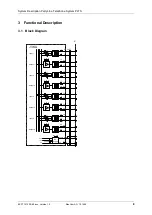
Testpoint 14 and 16
Output 1
Testpoint 17 and 19
Output 2
Testpoint 20 and 22
Output 3
Testpoint 23 and 25
Output 4
3.4 J3KA Potentiometers
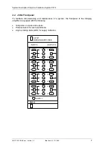
Twelve multiturn potentiometers are provided which allow individual adjustment of each input
to output path.
They are arranged in four groups of three potentiometers each as follows:
Group 1 controls signals from input 1.
Potentiometer 1 to output 2
Potentiometer 2 to output 3
Potentiometer 3 to output 4
Group 2 controls signals from input 2.
Potentiometer 1 to output 1
Potentiometer 2 to output 3
Potentiometer 3 to output 4
Group 3 controls signals from input 3.
Potentiometer 1 to output 1
Potentiometer 2 to output 2
Potentiometer 3 to output 4
Group 4 controls signals from input 4.
Potentiometer 1 to output 1
Potentiometer 2 to output 2
Potentiometer 3 to output 3
In addition to the potentiometers, jumpers are provided for range selection (see 4.2 below).
3.5 J3KA Light Emitting Diode
A
green LED on front panel (Light Emitting Diode) is provided which lits during normal
operation of the bridging amplifier. The LED turns on when sufficient supply voltage is present
for the voltage regulator to operate in its assigned range.


