33
We reserve the right to make changes without any prior notice.
Translation from original instructions
5.6 Refrigeration connections
The units using the refrigeration cycle often require a remote installation of the capacitor.
The cooling circuits equipped with shut-off valve, are charged in the factory with anhydrous nitrogen at a pressure of 12 bar.
Warning: the following operations require pressurised pipes and brazed connections to be made, and
these must be carried out by specialised staff in possession of the necessary qualifications in accordan
-
ce with current regulations.
5.6.1 Piping implementation
In order to lay the pipes, use hard or soft copper pipes, of a size suitable for the cooling capacity and the distance to be
covered and of an adequate thickness for the maximum designed pressure and the type of refrigerant used. Table 1 shows
the recommended diameters for equivalent lengths up to 50 m.
For greater distances, contact the manufacturer.
The route of the pipes must be as short and straight as possible, making sure the following basic rules are complied with:
- use the fewest number of bends possible, preferably as wide as possible;
-
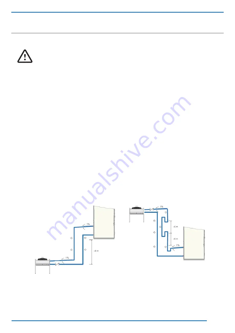
provide a slight slope of the flow line (1% downwards) in the horizontal sections in order to facilitate the passage of the
oil;
-
provide suitable syphons every 6 metres (5 metres for circuits with inverter-controlled compressor), in the vertical
stretches of the gas discharge pipe to the condenser, placing the first one immediately at the outlet of the unit;
-
maintain the gas discharge lines separate from the liquid back-flow one, if not isolated;
- support the horizontal and vertical lines with suitable vibration dampers;
- should the capacitor be placed in a higher position compared with the unit, install a non-return valve on the discharge
line near the input of the condenser; should the capacitor be placed in a lower position compared with the unit, install a
non-return valve on the liquid line near the output of the condenser;
- solder the joints, avoiding butt welds by using sleeves or enlarging the tubes;
-
adequately protect the various components such as valves or taps fitted nearby, e.g. by wrapping them with wet rags,
during braze-welding;
- once the junctions have been completed, blow-clean the tubes to remove any dirt;
- press the plant to search for any leaks.
Fig. 10 Separate section refrigerant connections


