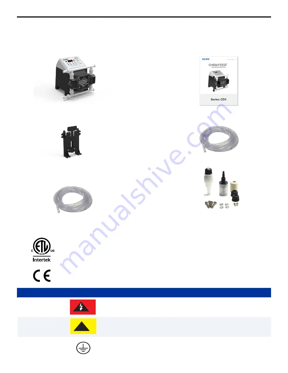
Blue-White CHEM-FEED CD1 Series Operating Manual Download Page 6

Page 6

4.0 

What’s In The Box

>

Smooth chemical dosing, no pulsation dampener needed

>

Diaphragm Failure Detection (DFD) system which senses diaphragm failure

>

Rated for continuous duty. 

>

Compatible with Blue-White Industries, Flow Verification Sensor (FVS) system. 

>

Remote Start/Stop

>

Relay outputs include a single 250V/3A and a single solid state. 

>

Multi diaphragm metering with industry best turndown at 2000:1

>

Built for long life at high pressures up to 150 PSI (10.3 bar)

>

Output rates up to 7.70 GPH (29.2 LPH).

>

Brushless DC motor.

4.1 

Agency Listings

This pump complies to the Machinery Directive 2006/42/EC, BS, EN 60204-1, Low Voltage Directive 
2014/35/EU BS EN 61010-1, EMC Directive 2014/30/EU, BS EN 50081-1/BS EN 50082-1.

This pump complies to the Machinery Directive 2006/42/EC, BS, EN 60204-1, Low Voltage Directive 
2014/35/EU BS EN 61010-1, EMC Directive 2014/30/EU, BS EN 50081-1/BS EN 50082-1.

Symbol

Description

Warning (Risk of electric shock)

Caution (Refer to the user’s guide)

Ground, Protective Conductor Terminal

!

ENCLOSURE RATING

NEMA 4X

  Constructed for either indoor or outdoor use to provide a degree of protection to personnel against incidental 

contact with enclosed equipment; to provide a degree of protection against falling dirt, rain, sleet, snow, 
windblown dust, splashing water, and hose-directed water; and that will be undamaged by external formation 
of ice on enclosure.

IP66


No ingress of dust; complete protection against contact. Water projected in powerful jets against  enclosure 

from any direction shall have no harmful effects.

Page 7

CHEM-FEED CD1

CHEM-FEED CD1

5.1 

Mounting Location


 1.    Choose an area located near the chemical supply tank, chemical injection point, and electrical supply. Also,     

choose an area where the pump can be easily serviced.


2.  Finding a secure surface and using the provided mounting hardware, mount the pump close to the injection  

point. Keep the inlet (suction) and outlet (discharge) tubing as short as possible. Longer discharge tubing 
increases back pressure at pump head.


NOTE

: Mounting the pump lower than the chemical container will gravity-feed chemical into it. This “flooded 

suction” installation will reduce output error due to increased suction lift. A shut-off valve, pinch-clamp, or 
other means to halt gravity-feed to the pump must be installed during servicing.


NOTE

: Install a back flow prevention check valve at the discharge side of the pump to prevent the system fluid 

from flowing back through pump during tube replacement or during tube rupture.


NOTE

: It is recommended to have a pressure relief valve at the discharge side of the of pump to prevent 

premature wear and damage to the pump tube, in the event that the discharge line becomes blocked.


NOTE

: The 

does not require back pressure. Keep the discharge pressure as low as possible to maximize 

pump 

the tube life.


5.0 

INSTALLATION

All diagrams are strictly for guideline purposes only. Always consult an expert before installing 
metering pump on specialized systems. Metering pump should be serviced by qualified persons 
only.

Always wear protective clothing, face shield, safety glasses and gloves when working on or near 
your metering pump.  Additional precautions should be taken depending on solution being 
pumped. Refer to MSDS precautions from your solution supplier.

Risk of chemical overdose. Be certain pump does not overdose chemical during backwash and 
periods of no flow in circulation system.

!

CAUTION

!

CAUTION

Be sure that installation does not constitute a cross connection with drinking water supply. 
Check your local plumbing codes.

The pump should be serviced by qualified persons only. If equipment is used in a manner not 
specified in this manual, the protection provided by the equipment may be impaired.

The pump should be supplied by an isolating transformer or RCD (operating current less or 
equal 30 mA).

!

CAUTION

!

CAUTION

!

CAUTION

!

CAUTION

CD1 Multi-Diaphragm Pump

Instruction Manual

Wall Mounting Bracket

Suction Tubing (3/8”x5’)

Discharge Tubing (3/8”x5’)

Parts Kit

!Injection Fitting

!Foot Valve

!Screws

!Ceramic Weight

!Tube Nuts

Summary of Contents for CHEM-FEED CD1 Series

Page 1: ...Multi Diaphragm Metering Pump Series CD1 CHEM FEED...

Page 2: ...Input V option only 9 5 4 Programming FVS Flow Verification Sensor 10 6 0 Power Connections 10 7 0 Touchpad Layout 11 7 1 IO Connection 12 8 0 Output Adjustment 14 9 0 Diaphragm Failure Detection DFD...

Page 3: ...Page 3 CHEM FEED CD1 READ THE INSTRUCTION MANUAL PRIOR TO INSTALLATION AND USE 1 714 893 8529 sales blue white com customerservice blue white com 5300 Business Drive Huntington Beach CA 92649...

Page 4: ...0 centipoise Maximum Suction Lift 20 ft at 0 PSI Ambient Operating Temperature O O O O 14 F to 115 F 10 C to 42 C Ambient Storage Temperature O O O O 40 F to 158 F 40 C to 70 C Operating Voltage 115V6...

Page 5: ...optional EP Ancillary Items Provided Suction Tubing 3 8 OD x 1 4 ID x 5 Clear PVC Discharge Tubing 3 8 OD x 1 4 ID x 5 Polyethylene LDPE Suction Strainer Polypropylene Weight Ceramic Enclosure Valox P...

Page 6: ...y Directive 2006 42 EC BS EN 60204 1 Low Voltage Directive 2014 35 EU BS EN 61010 1 EMC Directive 2014 30 EU BS EN 50081 1 BS EN 50082 1 Symbol Description Warning Risk of electric shock Caution Refer...

Page 7: ...n check valve at the discharge side of the pump to prevent the system fluid from flowing back through pump during tube replacement or during tube rupture NOTE It is recommended to have a pressure reli...

Page 8: ...ly serviced 10 Self Tap 2 X 4 50 in 11 43 cm Wall Mount Bracket Side View Mounted Pump Front View 2 Lower the pump so that the tab on the wall mount is inserted into the slot located on the back of th...

Page 9: ...lluminate Use arrow keys to toggle min mA value for the pump to operate at 4 Press 4 20mA Input button for MIN Speed light to illuminate 5 Use arrow keys to toggle MIN Speed value for the pump to oper...

Page 10: ...properly grounded grounding type receptacle Use the voltage for which the power cord is rated Do not strap together control input output cables and power cables When there is a power interruption the...

Page 11: ...LED LCD Readout 2 Rate Display Key 3 Flow Verification Sensor FVS Key 4 Remote Start Stop Key 5 Lock Out Key 6 Prime Key 7 Start Stop Key 8 Down Key 9 Up Key 10 Manual Speed Adjust 11 4 20mA 3 3 4 4...

Page 12: ...12 CHEM FEED CD1 Pump Right Side Panel Item Number Item 1 M12 Input Connector 1 2 M12 Input Connector 2 Included with CD1V ONLY 3 M12 Output Connector 4 USB C Connector 1 3 2 M12 connectors not includ...

Page 13: ...Stop N O Dry Contact Closure Open Stop Gnd Run P2 Ground DC Ground 0 VDC P3 FVS 15 VDC 60 mA To power FVS sensor P4 FVS DC Ground 0 VDC FVS Ground Input P5 FVS Signal Input Signal Input for FVS Signal...

Page 14: ...c Acid Sodium Hydroxide and many others System will not be triggered by water rain condensation etc or lubricants If system has detected chemical pump diaphragm must be replaced and pump head must be...

Page 15: ...ume responsibility for damage to pump that has been caused by chemical attack 10 2 Cleaning Pump Pump will require occasional cleaning especially Injection fitting Footvalve Strainer and pump head val...

Page 16: ...T CQE Kit contains One discharge fitting red and One suction fitting white Both fittings come with EP o rings installed KIT CQA Kit contains Kit contains One discharge fitting red and One suction fitt...

Page 17: ...e One 3 8 discharge tube One foot valve and strainer and One mounting bracket with screws KIT S15 Kit contains One 15 gallon tank One 3 8 suction tube One 3 8 discharge tube One foot valve and straine...

Page 18: ...0 131 CAM C 1500 S A 125 COMPLETE 1 10 90011 261 SCREW 5 16 18 X 50 L PHIL NYLON BLK 1 11 76002 034 CAP DFD 1 12 76001 966 STANDOFF HEX MALE FEMALE THREADED MACH 2 13 71010 745 COVER PUMPHEAD MOUNT AS...

Page 19: ...12 1 EXPLODED VIEW Page 19 CHEM FEED CD1 17...

Page 20: ...t temperature E05 Inverter Error Contact Blue White Industries 714 893 8529 techsupport blue white com E06 No Motor Connection Contact Blue White Industries 714 893 8529 techsupport blue white com E08...

Page 21: ...e enclose a brief description of the problem and proof of purchase Prepay all shipping and insurance cost COD shipments will not be accepted Damage caused by improper packaging is the responsibility o...

Page 22: ...ity polyethylene LPH Liters per hour mA Milliampere min Minute mL Milliliters MSDS Material Safety Data Sheet N C Normally Close N O Normally Open NPT National Pipe Thread NSF National Sanitation Foun...

Page 23: ...Page 23 CHEM FEED CD1...

Page 24: ...ive must not dispose of end of life EEE as unsorted municipal waste but use the collection framework available to them for the return recycle recovery of WEEE and minimize any potential effects of EEE...

Reviews: