Blue Sky International MK II Owner'S Manual Download Page 7

Page 7

6.  System Gain, Sub Offset and Leve� Overview

System Electrical Gain

The input stage of BMC MK II is designed for a maximum input level of +24dBu 
(balanced or unbalanced) before clipping. The output stage will also drive 
a balanced 10K Ohm load to a maximum of +24dBu. However, because the 
BMC can add up to +6dB of gain to a channel to balance the system, there 
are situations where the BMC will clip. For example you cannot take a +24dBu 
input, set the system gain at 0dB, add +6dB of calibration gain to the signal 
and get +30dBu on the output. The output amplifiers in the BMC will clip under 
these conditions. 

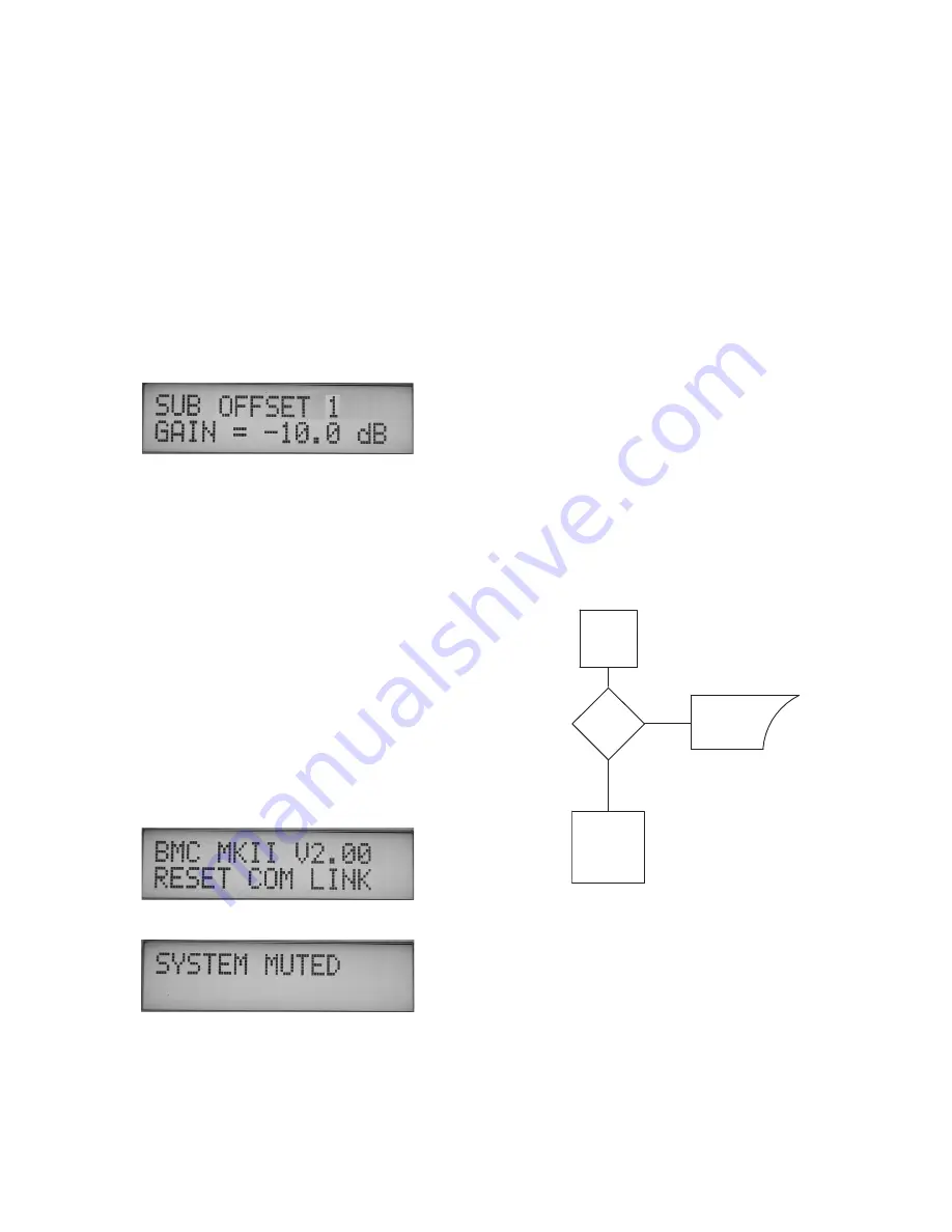
In  order  to  reduce  the  possibility  of  clipping  the  bass  /  LFE  summation 
output buss, the BMC MK II also offers a 0dB / -10dB “SUB GAIN” pad feature. 
Controlled via the remote, and located in the CAL CHANNELS menu (pictured 
below  -  see  the  “Software  Features”  section  on  page  8  and  9  for  more 
information),  this  feature  allows  the  user  to  add  a  -10dB  “pad”  on  the  SUB 
summation / output buss.

Although this may seem to be a limitation, in practice it is not. The Blue Sky 
monitors, like most amplified monitors, have relatively high voltage sensitivity. 
Therefore, there is quite a bit of flexibility in setting gains.

For the best signal to noise ratio and to minimize noise and hum pickup, the 
BMC should be driven with as high a signal level as possible. The output signal 
going to the monitors should be kept relatively high and if necessary signals 
should be attenuated at the monitors.

Calibration / Level Trims

The individual channel level trims (+/- 6dB) in the BMC MK II, are “OUTPUT” 
channel level trims, and are used to adjust the relative level between the SUB 
and SAT in .5 dB increments.  The reason this fact is important is because in 
certain applications, such as in a film setup where the surrounds may need to 
be at a lower level as compared to the front speakers, the level adjustments 
for  the  surrounds  must  be  done  before  the  signal  hits  the  BMC  MK  II.    This 
is because if you adjust the surround level only with the BMC main channel 
output level trims (main channels = L, C, R, LS & RS), the SUB and SURROUND 
level may not match.

1. 

Although the system will startup without the BMC remote being connected, 

in order to calibrate the system and gain full access to all of the BMC MK II’s 
features,  the  BMC  remote  must  be  connected  to  the  I/O  unit(s).  Once  the 
system has been calibrated, the remote can be disconnected and the main      
I/O  unit  will  retain  all  the  setup  information.  Once  the  systems’  power  is 
cycled, the main I/O unit will power up fully calibrated and at the “reference” 
position. See the “Software Features” section on page 8 and the “5.1 System 
Calibration” section on page 12 for more information.

2. 

The startup sequence is activated when ever a remote is connected to the 

I/O unit or when the power is cycled with the remote connected. The power 
up sequence is as follows -


A: 

The LEDs may flash momentarily as the remote receives power  


from the main I/O unit. The power LED on the front of the I/O  


unit(s) should be lit.


B: 

Within the I/O unit(s) the output relays will click on.


C: 

The LCD will display the current software version for 5 seconds.  


D: 

After the system has been fully activated the system will go into  


the mute mode and the display will show the following message.  


BMC MK II Power Up Sequence

IS

REMOTE

CONNECTED?

NO

LOAD

LAST STATE

REF GAIN

WAIT FOR

INSTRUCTIONS

FROM REMOTE

POWER UP

YES

7.  BMC MK II �ower U� Sequence

Summary of Contents for MK II

Page 1: ...B ue Sky Internationa 70 Sea Lane Farmingdale NY 11735 www abluesky com Owner s Manua Version 1b August 5 2005 Bass Management Controller MK II ...

Page 2: ..._ _ _ _ _ _ _ _ _ _ _ _ _ Page 7 8 Software Features_ _ _ _ _ _ _ _ _ _ _ _ _ _ _ _ _ _ _ _ _ Page 8 9 5 1 Speaker Placement _ _ _ _ _ _ _ _ _ _ _ _ _ _ _ _ _Page 10 10 5 1 System Wiring Information Diagram_ _ _ _ _Page 11 11 5 1 System Calibration _ __ __ __ __ __ __ __ __ Page 12 12 Additional Surround Setup Information_ _ _ _ _Page 15 13 Dual BMC MK II I O Unit Setup_ _ _ _ _ _ _ _ _ _ _ _ _Pag...

Page 3: ... of any kind on the product 11 SERVICING Do not attempt to service this product yourself Opening or removing covers including any over bottom or side speaker drivers may expose you to dangerous voltage or other hazards Refer all service to qualified service personnel 12 DAMAGE REQUIRING SERVICE Unplug this product from the wall outlet and refer servicing to qualified personnel under the following ...

Page 4: ...ner s Manual This manual addresses setup and operation of the Blue Sky BMC MK II This product includes several performance and operational changes when compared to the original Blue Sky BMC We ask that you read this owner s manual carefully heed all warnings and contact Blue Sky International if you have any comments or questions Contact information can be found on page 19 or you can visit www abl...

Page 5: ... 9 10 11 12 13 The Blue Sky BMC MK II has two operating modes These two modes are referred to as USER and SETUP Some of the buttons on the remote have two distinct functions depending on what mode the BMC MK II is operating in The Software Features on page 8 and 9 explains these functions in greater detail 1 RJ 11 Main BMC Control Output Connect this plug to the Main BMC I O unit with the supplied...

Page 6: ...ntrol Knob will bring the system out of the reference setting SETUP MODE In the PRESET MENU this key is used to change the letters in the CHANGE NAME preset sub menu See the Software Features section on page 8 and the 5 1 System Calibration Section on page 12 for more information 11 LS left surround SELECT Button USER MODE The LS button activates the solo function for the left surround output When...

Page 7: ...just the relative level between the SUB and SAT in 5 dB increments The reason this fact is important is because in certain applications such as in a film setup where the surrounds may need to be at a lower level as compared to the front speakers the level adjustments for the surrounds must be done before the signal hits the BMC MK II This is because if you adjust the surround level only with the B...

Page 8: ...MENU Moving the master gain control knob pressing mute or pressing the REF button again will bring the system out of the reference setting When the REF function has been activated the REF LED will be ON and the display will show REF GAIN and then state what that GAIN possition is 10dB in the example below For more information about how to detirmine the optimum reference level setting please follow...

Page 9: ...ARROW PRESET MENU The BMC MK II has a total of 4 presets available The presets store all level and calibration settings for the BMC along with preset name SUB level offset bass management IN OUT and LFE GAIN The main display will always display what PRESET is in current menu when in USER MODE and when not in MUTE REF or SOLO mode as shown below in this case PRESET 1 Whenever you are in the SETUP M...

Page 10: ...osition and slightly behind the mix position For larger rooms it may also be desirable to use multiple surround speakers as an array Satellite Speaker Monitoring Height Recommendations It is recommended that all of the satellite speakers be placed at or about seated ear height as shown in Figure 2 If it is not possible to place the speakers at or about seated ear height please aim the speakers at ...

Page 11: ...nnect your console workstation or other sources to your Blue Sky BMC MK II Foil shielded cables such as Belden 8451 8761 or 9501 should do quite well Other high quality cables are available and those that incorporate better shielding will yield an overall higher noise rejection lowering your systems susceptibility to external interference Another important tip to keep in mind when wiring your syst...

Page 12: ...ink noise Also please note that the LFE channel gain in a 5 1 system varies from 0dB to 10dB depending on the encoding format that is being used Since the LFE channel is not calibrated as a separate entity the LFE gain will not affect system calibration For more information about the LFE channel refer to page 15 Additional Surround and Setup Information The common calibration levels IMPORTANT NOTE...

Page 13: ... knob until the SYSTEM GAIN equals the gain noted in step 4 Release the knob being careful to not nudge it and then press YES when the menu reapears You have now successfully stored the preset REF level Press CANCEL to exit setup and then press the REF button to confirm the setting is correct The display will read REF GAIN with the gain setting below shown below The REF LED will also be ON SYSTEM ...

Page 14: ...the display reads MUTE CHANNELS as shown in step 1 Press the down arrow button one time or until the display reads MUTE SUB 1 Press the NO button on the remote The display will read MUTE SUB 1 NO as shown below Now MUTE the other 5 channels Left Center Right LS RS Step 6 Confirm that the gain knob on the remote is set to the REF setting as determined in the section titled SETTING REFERENCE GAIN on...

Page 15: ...lthough there may be some creative reasons to use the LFE from time to time It is important to note that no significant audio should be sent exclusively to the LFE channel The reason for this is that if a Dolby Digital audio track is folded down to 2 channels which can happen if a consumer doesn t have a surround system the LFE channel will not be added to the fold down mix all other channels will...

Page 16: ...where the bass is being routed from the MASTER I O Unit 1 to the AUX I O Unit 2 This can be any system beyond 5 1 and all the way up to 10 1 The general overview with regard to connections and setup is shown on page 17 Important notes for this type of setup 1 SUBWOOFER GAIN 1 should be set to 0dB in the CAL CHANNELS menu 2 Overall system subwoofer level should be set on the BMC I O unit connected ...

Page 17: ... ELECTRIQUE NE PAS OUVIR pm3 L U C A S F I L M R PUSH PUSH PUSH MAIN AUX LFE Input 10dB or 0dB Bass Managed LFE summed input from main BMC unit LFE should be set to 0dB of gain to sub to LFE IN MAIN BMC Unit 1 Wire the main channels to this BMC Subwoofer level trim should be set to 0dB Overall system subwoofer level should be adjusted on the AUX BMC via remote LFE gain can be set to either 10dB or...

Page 18: ...ype 2nd order Linkwitz Riley High Pass Filter Cutoff 80Hz Low Pass Filter Type 4th order Linkwitz Riley Low Pass Cutoff 80Hz LFE Input Gain 0dB 10dB Selectable Low Pass Filter 4th order 120Hz Input power 120 VAC 60HZ 240 VAC 50 60HZ 15 Watts Voltage set at the factory 14 Technical Information 1 10X GAIN 24 dB OCT 120 HZ LOWPASS DIGITALLY CONTROL ANALOG POT INPUT SELECT INPUT OUTPUT 24 dB OCT 80 HZ...

Page 19: ...due to non factory packaging 4 Include a legible note stating your name shipping address no P O boxes daytime phone number RA number and a detailed description of the problem including how it can be duplicated 5 Write the RA number on the top of the carton 6 Ship the product to the address below We recommend United Parcel Service UPS Please insure the product regardless of shipping method Blue Sky...

Page 20: ...Blue Sky International 70 Sea Lane Farmingdale NY 11735 www abluesky com ...

Reviews: