VISION
D R I V E R S H A N D B O O K
116
6.5 Repeat the procedure for the spring brake chamber on the oppo-
site side of the bus. The spring brakes are now released, having their
springs compressed by the release bolts.
7. With the axle shafts removed and air spring brakes caged, the bus is prepared
for towing. The Vision may be equipped with optional tow hooks, located
just inside the access openings of the front and/or rear bumper. Appendix
1 of the Front Axle & Suspension chapter contains additional information
about towing procedure.
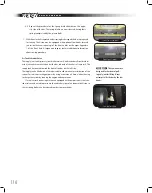
Air Tank schrader Valve
The supply (wet tank), primary (rear brake reservoir), and secondary (front brake res-
ervoir) air tanks are mounted under the bus, inboard of the chassis frame rails. The
supply tank is mounted toward the front of the bus on the left side.
The supply tankis fitted with a Schrader valve to allow manual pressurization of the
system for service or testing purposes by using a common air hose, without having
to charge the system by running the engine and compressor.
If a service truck rendering asistance is equipped with compressed air, the Scha-
rader valve can be used to pressurize the air brake system of an inoperative Vision, so
that its spring brakes can be released in order to move the bus.
Front Tow Hooks
Rear Tow Hooks
Schrader Valve
[WARNING]
The tow hooks are
designed for horizontal pull-
ing only; not for lifting. Never
attempt to lift the bus by the tow
hooks.
Summary of Contents for VISION 2011
Page 1: ...10013333 2011 BBCV D R I V E R S H A N D B O O K 10013333 BBCV BLUE BIRD VISION 2011 ...
Page 2: ......
Page 3: ...10013333 Revision B ...
Page 8: ...VISION D R I V E R S H A N D B O O K 6 ...
Page 26: ...VISION D R I V E R S H A N D B O O K 24 ...
Page 70: ...VISION D R I V E R S H A N D B O O K 68 ...
Page 137: ...135 Notes n o t e s ...
Page 138: ...VISION D R I V E R S H A N D B O O K 136 Notes ...
Page 139: ......
Page 140: ...10013333 2011 BBCV D R I V E R S H A N D B O O K 10013333 BBCV BLUE BIRD VISION 2011 ...


