6
Operating Instructions and Parts Manual
INSTALLATION (CONTINUED)
CONVERTING THE DEEP WELL PUMP TO SHALLOW WELL
OPERATION (FIGURE 8)
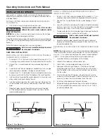
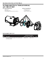
For shallow wells (25 feet or less), a bolt-on shallow well jet is available as
an accessory for deep well pumps. The jet attaches to the front of the
pump with the two bolts provided and converts the deep well pump into
a shallow well pump. The shallow well jet has a 1 in. NPT inlet and a 1/8
in. NPT opening for an air volume control. For optimum performance, an
inline check valve on the inlet side of the shallow well jet is recommended.
ELECTRICAL
Risk of electrical shock. This pump is designed
for indoor installation only.
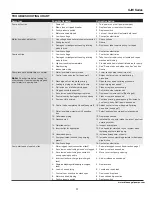
Select the proper size wire and fuse (Chart 2). Time delay fuses are
recommended over standard fuses for motor circuit protection. All pump
motors have built-in automatic overload protection that will prevent
damage to the motor due to overheating.
Do not connect to electric power supply until
unit is permanently grounded. Connect ground
wire to approved ground then connect terminal provided.
A metal underground water pipe or well casing at least 10 feet long
makes the best ground electrode. If plastic pipe or insulated fittings
are used, run a wire directly to the metal well casing or use a ground
electrode furnished by the power company.
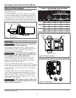
There is only one proper ground terminal on the unit. The terminal is
located under the pressure switch cover, is painted green and is identified
as GRD. The ground connection must be made at this terminal (Figure 9).
The ground conductor must not be smaller than the circuit conductors
supplying the motor.
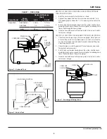
The voltage of power supply must match the voltage of the pump.
The unit has dual voltage motors preset at the factory to 115 volts. The
motors can be converted to 230 volts by turning the voltage selector to
the desired voltage (see Figure 10, on page 6). Disconnect power, use
needle nose pliers to pull the selector out approximately 1/4 in., rotate,
and then reinsert in correct position.
Disconnect power and release all pressure from
the system before attempting to install, service,
relocate or perform any maintenance.
CHART 2 - RECOMMENDED FUSE AND WIRING
DATA - 60 HZ MOTORS
HP
Volt
Dual
Element
Fuse
250V
Distance in Feet
From Meter to Motor
0
51
101
to
to
to
50
100
200
Wire Size
1/2
115
20
14
12
10
230
10
14
14
14
3/4
115
20
14
12
8
230
10
14
14
14
1
115
20
14
12
8
230
10
14
14
14
Figure 10 - Voltage Selector
230 V
115 V
L2
3
L1
1
Figure 9 - Electrical Connections
MOTOR
LINE
GROUND
SCREW
Figure 8 - Shallow Well Jet
TO AIR VOLUME CONTROL
JET ASSEMBLY
www.blueangelpumps.com


