background image

Manual

Roboost Roof Tiles Landscape

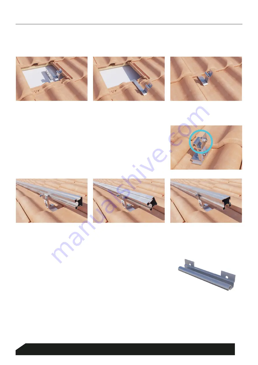
Place the mounting profile against the roof hooks and rotate the mounting 
profile around the rotation element of the roof hook. Ensure that the 
profiles left and right are aligned.

Insert a hammer-head screw with lock nut into the 

outermost

 roof hooks.

STEP

 4

STEP

 5

The hammer-head screw is now engaged in the mounting profile. Tighten the lock nut onto the hammer-head 
screw of the outermost roof hook, so that the profile can no longer rotate or slip free from the roof hook.

PROFILE COUPLING

If necessary, fit a profile coupling to connect two mounting profiles. Rotate 
the profile coupling into the mounting profiles.

STEP

 6

MOUNTING PROFILE

Slide the roof tile above, where the roof hook is to be fitted, upwards or remove it. Then slide the roof hook over 

the lower part of the roof tile and batten, and replace the top roof tile in its original position.

STEP 3

3

Blubase 

|

 Lingenstraat 9 

|

 8028 PM Zwolle, Nederland 

|

 T. (+31) 085-8000 501 

|

 [email protected] 

|

 www.blubase.com

Summary of Contents for roboost Roof Tiles Landscape

Page 1: ...Roof Tiles Landscape Manual ...

Page 2: ...nto account that the mounting profile should not extend more than 200mm beyond the outermost roof hook and that the distance between the solar panels and the roof edge should be 500mm at all times STEP 1 Adjust the gap between the lower and middle part of the roof hook in such a way that the roof hook clamps lightly when pushed over the roof tile and roofing batten STEP 2 We advise the use of an a...

Page 3: ...er head screw of the outermost roof hook so that the profile can no longer rotate or slip free from the roof hook PROFILE COUPLING If necessary fit a profile coupling to connect two mounting profiles Rotate the profile coupling into the mounting profiles STEP 6 MOUNTING PROFILE Slide the roof tile above where the roof hook is to be fitted upwards or remove it Then slide the roof hook over the lowe...

Page 4: ... an end clamp to the ends Caution The tightening torque of the screw connection is 9 Nm STEP 9 Hook in the universal clamp behind the lip on top of the hammer head chamber see illustration STEP 9 1 Check that the clamp is securely in place as illustrated STEP 9 3 Slide the clamp towards the panel STEP 9 4 Twist the clamp smoothly over the rail until it clicks into place on the other side of the ha...

Page 5: ...ce the second panel on top of the mounting profiles STEP 10 Install an intermediate clamp in between the panels Press the panels tightly against the intermediate clamp Caution The tightening torque of the screw connection is 9 Nm STEP 11 All panels are clamped at four points STEP 9 5 5 Blubase Lingenstraat 9 8028 PM Zwolle Nederland T 31 085 8000 501 info blubase nl www blubase com ...

Page 6: ...6702 NEN7250 NEN1991 1 4 A1 C2 2011 NB 2011 and NPR 6708 2013 in particular for wind snow and water loads The building insurer must be contacted in advance The following building related elements should be checked and approved in view of the existing structural arrangements The additional weight load of the entire PV system that will be installed Geometry change of the roof surface Wind pressure s...

Reviews: