background image

INSTALLATION INSTRUCTIONS 

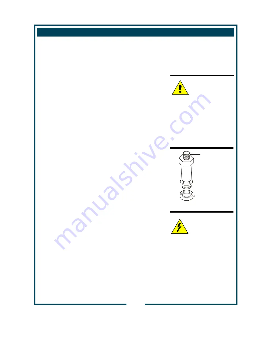
INSTALL LEGS 

 
The brewer is provided with 4" adjustable legs and rubber feet.  Be 
sure the legs are securely screwed into the base of the brewer, and 
that the rubber feet are properly installed. 


LEVEL THE UNIT 

 
The adjustable legs allow the brewer to be leveled.  Set the brewer 
in its ultimate operating location and check for level with a spirit 
level  Adjust the brewer for level from front-to-rear, and from side-
to-side.  Be sure all four feet rest firmly on the counter. 
 

PLUMBER’S INSTALLATION INSTRUCTIONS 

 
IMPORTANT: 

This equipment must be installed in accordance with the Basic 
Plumbing Code of the Building Officials and Code Administrators 
International (BOCA), and the Food Service Sanitation Manual of 
the Food and Drug Administration (FDA).  Also, this equipment   
installation must comply with all local plumbing codes and            
ordinances. 


IMPORTANT:   

Brewer must be installed on a water line with a full-flow pressure 
between 20 psi and 90 psi. 

 
NOTE:  

If water pressure varies greatly, or exceeds 90 psi at any 

time, a water pressure regulator must be installed.  Plumbing 
installer must supply the regulator.  

 
Brewer must be connected to a potable water supply.  Bloomfield 
recommends not less than 1/4” copper tubing for installations of 12’ 
or less, and not less than 3/8” copper tubing for installations        
exceeding 12’.  Brewer must be connected to a COLD water line. 


NOTE:  

DO NOT use a saddle tap for this water line connection. 

 
A shut-off valve must be installed between the main water supply 
and the brewer.  Plumbing installer must supply the shut-off valve.  
A 1/4-turn ball valve is recommended. 

 
Bloomfield highly recommends the use of the provided water 
strainer to help prevent deposits in the brewing system. 

 
Flush the water line before connecting to the brewer. 
 

ELECTRICIAN’S INSTALLATION INSTRUCTIONS 

 
Brewer requires a dedicated single-phase circuit: 

 
Model 9220        120/208 Volt AC, 60 Hz 30 Amp circuit 
                          3-Wire (L1, L2, N plus Gnd) 

 
Model 9221        120/240 Volt AC, 60 Hz 30 Amp circuit 
                          3-Wire (L1, L2, N plus Gnd) 

NOTE: 

To enable the installer to make 
a quality installation and to   
minimize installation time, these 
tests and suggestions should 
be completed before the actual  
installation is begun. 


CAUTION:   

Hazard from 
Unstable Equipment


Rubber feet must be installed 
on each leg of the brewer.  
Legs must be adjusted so that 
all four feet rest firmly on the 
counter.  Failure to properly  
install the feet can result in 
movement of the brewer, which 
can cause personal injury and/
or damage to the brewer. 


Fig. 2  Adjustable Legs 


CAUTION: 

Electric Shock    
Hazard  


Brewer must be properly 
grounded to a reliable earth 
ground to prevent possible 
shock hazard.  Do not assume 
a plumbing line will provide 
such a ground.  Electrical shock 
may cause serious injury. 

SCREW INTO
BREWER
FRAME

ADJUST
FOR
HEIGHT

ATTACH
RUBBER
FEET

Summary of Contents for 9220

Page 1: ...1 OWNERS MANUAL for SS2 SERIES DUAL SATELLITE COFFEE BREWERS with ELECTRO MECHANICAL CONTROL and EXTERNALLY HEATED SATELLITE SERVERS MODEL 9220 9221 Includes Installation Operation Use Care Servicing Instructions Model 9221 Dual Satellite Brewer ...

Page 2: ... coffee carry a 90 days parts warranty only excludes decanters THE FOREGOING OBLIGATION IS EXPRESSLY GIVEN IN LIEU OF ANY OTHER WARRANTIES EXPRESSED OR IMPLIED INCLUDING ANY IMPLIED WARRANTY OF MERCHANTABILITY OR FITNESS FOR A PARTICULAR PURPOSE WHICH ARE HEREBY EXCLUDED BLOOMFIELD INDUSTRIES DIVISION SPECIALTY EQUIPMENT MANUFACTURING CORPORATION SHALL NOT BE LIABLE FOR INDIRECT INCIDENTAL OR CONS...

Page 3: ...in or repair the appliance in a manner which will ensure its optimum performance WARRANTY STATEMENT xi SPECIFICATIONS 1 FEATURES OPERATING CONTROLS 2 PRECAUTIONS GENERAL INFORMATION 4 AGENCY APPROVAL INFORMATION 4 INSTALLATION 5 OPERATION 7 CLEANING INSTRUCTIONS 10 PROGRAMMING INSTRUCTIONS 12 TROUBLESHOOTING SUGGESTIONS 17 SERVICING INSTRUCTIONS 18 EXPLODED VIEWS 20 WIRING DIAGRAM 24 SATELLITE 25 ...

Page 4: ...FEATURES AND OPERATING CONTROLS 2 Fig 1 SS 2 Satellite Brewing System Features Operating Controls ...

Page 5: ...acturer model and serial number Also lists voltage and wattage rating of brewer Glows when the tank water is up to temperature Located on lower right rear of brewer Turns main power to brewer ON or OFF Positions externally heated satellite on brewer Maintains temperature of product in satellite Control individual warmers for externally heated satellite Holds coffee grounds during brew cycle Forms ...

Page 6: ...or wiring Any procedure which requires the use of tools must be performed by a qualified technician This manual is considered to be a permanent part of the appliance This manual and all supplied instructions diagrams schematics parts breakdown illustrations notices and labels must remain with the appliance if it is sold or moved to another location This appliance is made in the USA Unless otherwis...

Page 7: ...r installations exceeding 12 Brewer must be connected to a COLD water line NOTE DO NOT use a saddle tap for this water line connection A shut off valve must be installed between the main water supply and the brewer Plumbing installer must supply the shut off valve A 1 4 turn ball valve is recommended Bloomfield highly recommends the use of the provided water strainer to help prevent deposits in th...

Page 8: ...ecure and leak proof 1 CHECK BREWER FOR PROPER CONFIGURATION Make sure spray disk gaskets are in place INSIDE of spray heads Make sure spray disks are properly installed Check hot water faucet for proper operation and leaks Place empty satellites in position 2 START BREWER OPERATION Be sure HEATER ON OFF switch is OFF then press POWER SWITCH on back of unit to energize brewer Water Inlet Solenoid ...

Page 9: ...at the gaskets are properly installed inside the spray heads Check the brew chambers Check that the brew chambers are clean Check that the bypass diverters are properly installed in the brew chambers START UP Press POWER SWITCH back of brewer to ON Brewer water tank will begin filling When tank stops filling press HEATER ON OFF switch to ON READY TO BREW light will glow when water is at proper tem...

Page 10: ...ne brew chamber under each brew head Insert Satellites Slide one satellite under each brew chamber until it is fully seated Press appropriate WARMER SWITCH to ON Select Brew Volume Press VOLUME SELECT switch to 1 GAL or 1 1 2 GAL Start the Brew Press either the right or left START BREW key NOTE The brew can be cancelled at any time by pressing the BREW STOP key At the end of the brew be sure all w...

Page 11: ... tee Bypass water flows through the brew basket but is diverted from the grounds by a bypass channel The remainder of the brew water is discharged through the SPRAY DISK and flows over the grounds in the brew basket Each half of the brewer is independently controlled HOT WATER FAUCET The HOT WATER FAUCET is fed by gravity from the hot water tank The faucet is spring loaded closed and manually open...

Page 12: ...e inside of spray head and area around spray head with a soft clean cloth or sponge moistened with clean water 6 Wash spray disks in a sink using warm water and a mild detergent A bristle brush may be used to clear clogged spray holes Rinse spray disks with clean water and allow to air dry 7 Wash brew baskets in a sink using warm water and a mild detergent A bristle brush may be used to clean arou...

Page 13: ...ard Then pull ears forward Lift guard off of retaining clip b Remove sight glass tube from silicone elbow Run the sight glass brush through the tube at least ten times c Reassemble the tube to the silicone elbow Be sure the elbow has not been pulled from the satellite body d Reinstall the sight glass guard 6 Reinstall lids Install satellites on brewer 7 Rinse satellites With an empty brew chamber ...

Page 14: ... panel then remove the tank lid assembly Do not disconnect the tank assembly at this time 3 Siphon all water from the hot water tank 4 Mix 10 gallons of deliming solution according to the manufacturer s directions Carefully pour the deliming solution into the water tank Lower the lid assembly back onto the tank Allow to sit for 30 minutes or as directed by the chemical manufacturer 5 At end of soa...

Page 15: ...pray disks 13 Reconnect brewer to electrical supply 14 Install the brew chamber without filter paper or grounds 15 Place an empty satellite under the brew chamber Run at least five 1 1 2 gallon brew cycles and discard all water generated at the end of each cycle Repeat for the other side 16 Rinse satellite with clean water Reinstall one empty satellite under each brew chamber Brewer is ready to us...

Page 16: ...r container to calibrate volume 1 Press HEATER ON OFF switch to OFF Turn POWER switch on back of brewer OFF 2 Remove TOP PANEL Operating controls are accessible through the top panel only 3 Adjust the TIMER setting NOTE Each side has its own timer The LEFT TIMER is for the LEFT SIDE the RIGHT TIMER is for the RIGHT SIDE Turn CLOCKWISE to increase time Turn COUNTER CLOCKWISE to decrease time Adjust...

Page 17: ... switch on back of brewer OFF 2 Remove TOP PANEL Operating controls are accessible through the top panel only 3 Remove one of the plugs in the tank cover and insert a thermometer of known accuracy 4 Locate the CONTROL THERMOSTAT on the right side of the top housing Turn CLOCKWISE to increase temperature Turn COUNTER CLOCKWISE to decrease temperature 1 8 turn is equal to approximately 10ºF change 5...

Page 18: ...s Too many paper filters or wrong filter used Use one genuine Bloomfield paper filter per brew Chamber discharge hole plugged Clean brew chamber Timer not set properly Set timer Too much coffee or too fine a grind Check with coffee supplier for recommended grind and quantity Heats slow Connected to wrong voltage Verify supply voltage Scale build up on heating elements De lime hot water tank Damage...

Page 19: ...ARD 1 4 86577 FAUCET SHANK ASSY 1 4 1 86600 FAUCET MODEL ESP 1 4 2 8700 25L SEAT CUP 3S10 1 4 3 84392 HANDLE 13SBE SNAP 1 4 4 84394 C RING 18 1 1 4 5 8600 26 NUT HEX 1 4 6 84395 SHANK 1 5 84299 HOUSING SIGHT GAUGE 1 6 84300 BRACKET SIGHT GAUGE 1 7 84354 TUBE SIGHT GAUGE 1 8 8043 13 ELBOW 1 9 SCREW 8A x 1 2 TRS HD ST BLK 4 10 SCREW 8A x 1 2 TRS HD ST SS 2 11 DECAL SATELLITE 1 4 7 84489 WASHER FIBRE...

Page 20: ...EXPLODED VIEW CABINET AND EXTERIOR COMPONENTS 18 ...

Page 21: ...P ON NONE ON 10A 2 23 82395 SWITCH LIGHTED 20A 250V 1 24 84098 SWITCH 2P 50A 1 25 LOWER HOUSING 1 26 COVER TOP HOUSING 1 27 FRONT PANEL 1 28 PLATE BOTTOM ASSY 1 29 BASE ASSY 1 30 84623 TIMER FULL 2 3 1 3 2 ITEM P N DESCRIPTION QTY 31 WELDMENT WARMER BASE 1 32 HOUSING UPPER ASSY 1 33 84382 SWITCH ROCKER HI TEMP 2 34 SCREW 8A x 1 2 TR TAP SS 40 35 82533 BREW CHAMBER ASSY SS O P T I O N A L 35a 82387...

Page 22: ...EXPLODED VIEW INTERIOR COMPONENTS 20 ...

Page 23: ...0º BEND 1 15 83312 THERMOSTAT HI LIMIT 2P 1 16 TANK LID ASSY 1 17 84630 TUBE SILICONE 50 ID x 4 25 2 18 8043 11 ELBOW OUTLET 2 19 83384 TUBE VENT EXTENSION 4 2 ITEM P N DESCRIPTION QTY 20 83537 TUBE SILICONE 9 1 21 83388 VALVE DISPENSING ADJUST 2 22 82148 LOCK WASHER 1 23 55485 NUT 1 4 20 pk 100 1 24 SCREW 8A x 1 2 TR TAP SS 4 25 86280 THERMOSTAT 15 CAP TUBE 1 26 83414 SHIELD HI LIMIT THERMO 1 27 ...

Page 24: ...22 WIRING DIAGRAM ...

Page 25: ...23 NOTES ...

Page 26: ...rier Commercial Refrigeration In US and Canada Telephone 775 689 5700 Fax 888 492 2783 Fax 800 356 5142 website www wellsbloomfield com for orders only Bloomfield Industries proudly supports CFESA Commercial Food Equipment Service Association ...

Reviews: