background image

Lit. No. 43991, Rev. 01 

13 

November 1, 2012

MOUNTING THE SPREADER

RECEIVER MOUNT SPREADER

NOTE: The spreader shall be installed according 
to instructions supplied. Your local outlet is 
trained to provide this service and service your 
spreader with factory original parts.

1.  Attach the spreader to the receiver mount with six 

3/8"-16 x 1" cap screws.

2.  Insert the assembled unit into the receiver hitch 

and secure with pin (not included).

3.  Plug the spreader harness into the vehicle 

harness.

4.  Use the supplied ratchet straps to secure the 

assembly to the vehicle frame.


Attaching the straps to the vehicle bumper or 
tailgate may result in vehicle or spreader damage.


CAUTION

During removal or mounting, securely grip 
spreader to avoid dropping.

SWING AWAY

®

 SPREADER

NOTE: The spreader shall be installed according 
to instructions supplied. Your local outlet is 
trained to provide this service and service your 
spreader with factory original parts.

1.  Fasten the left and right top brackets along with 

any shims to the truck bed rail with two 1/2" cap 
screws, two 1/2" 

fl

 at washers and two 1/2" locknuts 

per bracket. Install the two 5/16" cap screws and 
locknuts to the side of the top brackets.

2.  Place the left and right base plates on the bumper 

of the truck and line up with the holes in the bumper.

3.  Attach the base plates to the bumper using three 

3/8" cap screws, three 3/8" plain washers, any 
shims and three 3/8" locknuts per side.

4.  Place the spreader on the base plates and insert 

the hinge pins. Secure the hinge side by installing 
one 1/4" cap screw and 1/4" locknut through the 
hole in the base plate boss and hinge pin.

5.  Install hitch pin clip through the base plate boss 

and the removable hinge pin.

6.  Plug the spreader harness into the vehicle harness.

7.  Plug the center high mounted stoplight (CHMSL) 

cord into the vehicle stoplight harness.

 CAUTION

During removal or mounting, securely grip 
spreader to avoid dropping.

Summary of Contents for 94444

Page 1: ...with an earlier date CAUTION Read this manual before installing or operating the spreader This manual is for BLIZZARD LP 8 Tailgate Spreaders with serial numbers beginning with 090324 and higher Low P...

Page 2: ......

Page 3: ...ame ______________________________________________ Phone _________________________ Dealer Address _____________________________________________________________________________ Vehicle Model Year _____...

Page 4: ......

Page 5: ...er 13 SWING AWAY Spreader 13 OPERATING THE SPREADER 14 Driving and Spreading on Snow and Ice 14 Variable Speed PWM Control 14 Starting and Stopping the Motor 14 Adjusting the Spinner Speed 15 Blast Ma...

Page 6: ...elp ensure profitable and trouble free operation of your spreader Keep this manual accessible It is a handy reference in case minor service is required When service is necessary bring your spreader to...

Page 7: ...stop then lock out power Do not climb into or ride on spreader CAUTION If rear directional CHMSL light or brake stoplights are obstructed by the spreader the lights shall be relocated or auxiliary dir...

Page 8: ...d in the Maintenance section of this Owner s Manual PERSONAL SAFETY Remove ignition key and put the vehicle in park or in gear to prevent others from starting the vehicle during installation or servic...

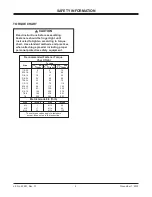
Page 9: ...7 8 9 150 378 591 1 8 220 583 893 Metric Grade 8 8 ft lb Size Torque Size Torque M 6 7 M 12 60 M 8 17 M 14 95 M 10 35 M 16 155 These torque values apply to fasteners except those noted in the instruct...

Page 10: ...des SAFETY INFORMATION Warning Label receiver mount only Caution Label both sides SWING AWAY mount only WARNING CAUTION LABELS Please become familiar with the Warning and Caution labels on the spreade...

Page 11: ...1 2012 Code Definition YY 2 Digit Year MM 2 Digit Month DD 2 Digit Day LL 2 Digit Location Code XXXX 4 Digit Sequential Number ZZZZZZ 5 7 Digit Assembly PN SERIAL NUMBER LABEL YYMMDDLLXXXXZZZZZ YYMMD...

Page 12: ...in an accident or damage Do not exceed GVWR or GAWR ratings as found on the driver side vehicle door cornerpost WARNING New untitled vehicle installation of a spreader requires National Highway Traff...

Page 13: ...ed to provide this service and service your spreader with factory original parts 1 Fasten the left and right top brackets along with any shims to the truck bed rail with two 1 2 cap screws two 1 2 fla...

Page 14: ...yers Keep your windshield and all glass on your vehicle clean to see around you Dress properly for the weather Wear layers of clothing as you get warm you can take off layers CAUTION Drinking and then...

Page 15: ...th the motor or wiring is detected The light will flash a number of flashes in a row pause then repeat Count the flashes to determine the nature of the malfunction and refer to the diagnostic chart be...

Page 16: ...nd remove both hinge pins 5 Remove the spreader from the vehicle and stand in an upright position This may require additional support Removing the Top Brackets 1 Remove the two 1 2 cap screws washers...

Page 17: ...of the motor cap assembly seal This seal is very important to the reliability of the unit Replace the seal if needed 7 Check the condition of the spinner disk If the vanes are excessively worn the un...

Page 18: ...ews and replace the motor cap CAUTION Overtightening the belt may result in damage to the motor or bearings Phillips Head Screws Belt deflects approx 3 8 MAINTENANCE POSTSEASON MAINTENANCE Before stor...

Page 19: ...rts made of plastic shall be disposed of in customary manner BEARING AND SET SCREW MAINTENANCE Disconnect the electrical plug between the spreader and the truck before performing any maintenance 1 Tig...

Page 20: ...oom Tubing 14 ga Yellow Accessory Circuit Not used Not used 30 Amp Fuse 10 ga Red To vehicle ignition accessory wire or fuse box 14 ga Red 6 Amp Fuse Two Way Molded Connector Motor Specification 12 Vo...

Page 21: ...as required Speed control dial on the cab control does not change motor speed 1 Malfunctioning cab control 1 Replace cab control 2 Red and white connectors are incorrectly hooked up 2 Reconnect so red...

Page 22: ...n pulley set screw or replace pulley if damaged 4 Spinner pulley is not secured to spinner shaft 4 Replace cap screw and nut if missing or damaged Replace pulley if damaged 5 Spinner shaft bearings ar...

Page 23: ......

Page 24: ...rovement policy to change construction or design details and furnish equipment when so altered without reference to illustrations or specifications used Blizzard or the vehicle manufacturer may requir...

Reviews: