


12
3134980 03/13
Operating Instructions
Handling and Operation
GB
5
Handling and Operation
5.1 GA I
Adjustment of supporting points
preset adjusting screws (Fig.5/1)
Adjustment of the incline
• If plate is loaded incline cannot be adjust
-
ed with this model.
Securing of load
• Devices for securing of the load are not
part of the range of supply.
1
Fig. 5:
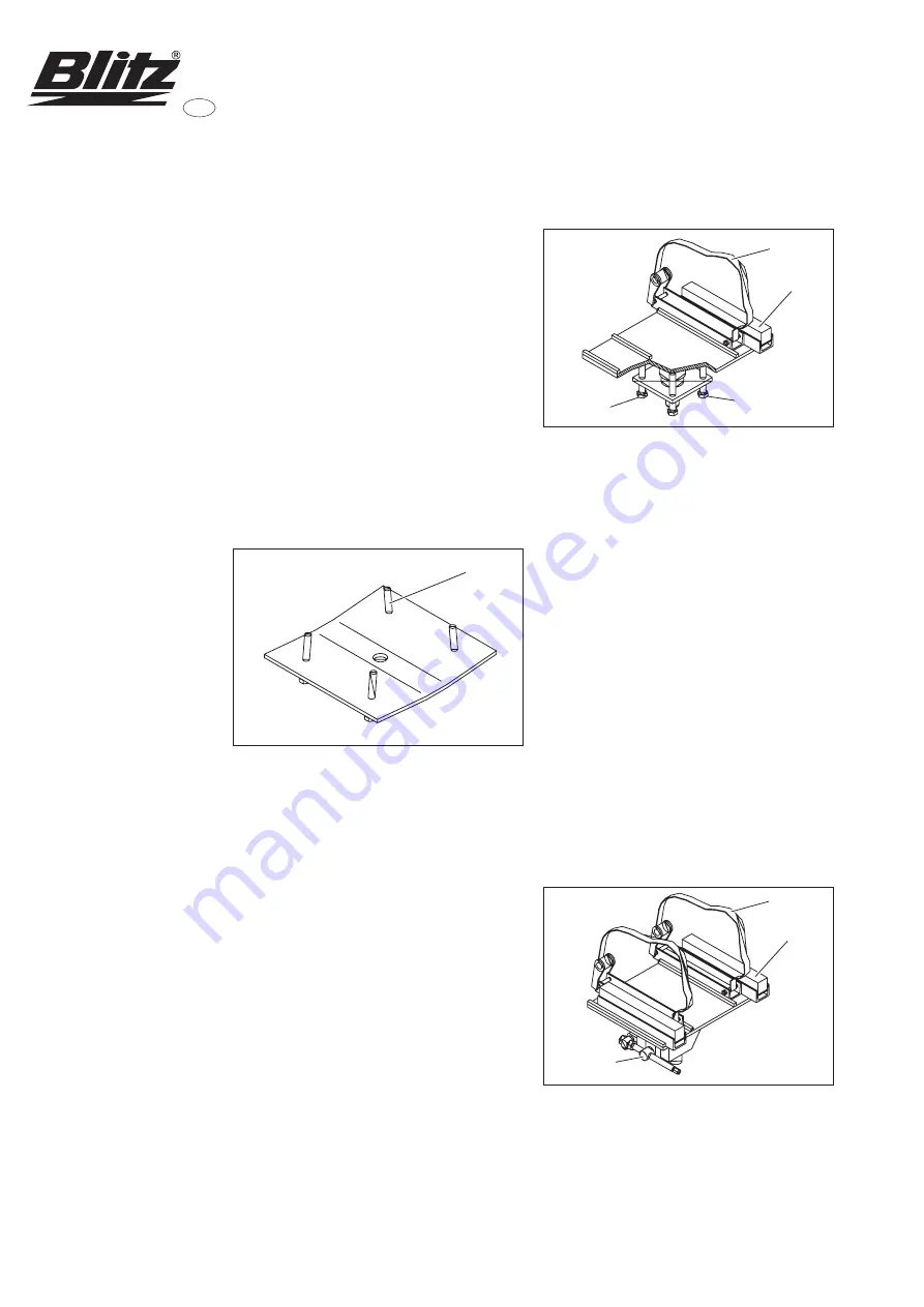
5.2 GA II
Adjustment of supporting points
loosen clamping screws (Fig.6/4) of the
sliding pieces
adjust desired width
clamp sliding pieces
Adjustment of the incline
• Incline is freely adjustable into all direc
-
tions by means of adjustment screws.
• Change incline diagonally step by step:
first loosen screw (Fig.6/2) and then adjust
screw (Fig.6/3) etc.
• Use a fork spanner SW 24.
Securing of load
• Securing of the load is effected by nylon
belts. The flexible hose is made to protect
the belts at sharp-edged loads.
5
4
3
2
Fig. 6:
5.3 GA III
Adjustment of supporting points
loosen clamping screws (Fig.7/4) of the
sliding pieces
adjust desired width
clamp sliding pieces
Adjustment of the incline
• Incline is freely adjustable into all direc
-
tions by means of adjustable gears.
• Use a fork spanner SW 17 to adjust the
spindle to the desired axle.
Securing of load
• Securing of the load is effected by nylon
belts. The flexible hose is made to protect
the belts at sharp-edged loads.
5
4
6
Fig. 7:
Summary of Contents for GA I
Page 2: ......
Page 21: ......
Page 35: ......
Page 43: ...37 3134980 03 13 2 2 1 BLITZ BLITZ BLITZ 2 2 BLITZ 3...
Page 44: ...38 3134980 03 13 1 2 3 1 3 3 4 3 2...
Page 47: ...41 3134980 03 13 5 4 GA IV GA Pkw 9 7 9 8 5 9 8 5 7 8 9 5 5 10 11 12...
Page 48: ...42 3134980 03 13 6 708820 708824 1 2 3 10 5 6 180 11...
Page 49: ......