


www.blaubergventilatoren.de
vento eco(2) a50-4 Pro
2
SAFETY REQUIREMENTS
• Please read the user’s manual carefully prior to installing and operating the unit.
• All user’s manual requirements as well as the provisions of all the applicable local and national construction, electrical, and technical
norms and standards must be observed when installing and operating the unit.
• The warnings contained in the user’s manual must be considered most seriously since they contain vital personal safety
information.
• Failure to follow the rules and safety precautions noted in this user’s manual may result in an injury or unit damage.
• After a careful reading of the manual, keep it for the entire service life of the unit.
• While transferring the unit control, the user’s manual must be turned over to the receiving operator.
CONTENTS
This user’s manual is a main operating document intended for technical, maintenance, and operating staff.
The manual contains information about the purpose, technical details, operating principle, design, and installation of the
Vento Eco(2) A50-4 Pro unit (-s) and all of its (their) modifications.
Technical and maintenance staff must have theoretical and practical training in the field of ventilation systems and should be able to
work in accordance with workplace safety rules as well as construction norms and standards applicable in the territory of the country.
The information in this user’s manual is correct at the time of the document’s preparation.
The Company reserves the right to modify the technical characteristics, design, or configuration of its products at any time in order to
incorporate the latest technological developments.
No part of this publication may be reproduced, stored in a retrieval system, or transmitted, in any form or by any means in any information
search system or translated into any language in any form without the prior written permission of the Company.
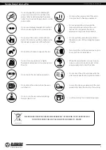
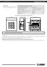
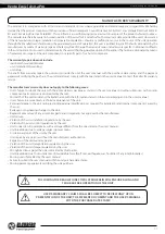
UNIT INSTALLATION AND OPERATION SAFETY PRECAUTIONS
• Disconnect the unit from power mains prior
to any installation operations.
• Unpack the unit with care.
• The unit must be grounded!
• While installing the unit, follow the safety
regulations specific to the use of electric
tools.
Safety requirements ..................................................................................................................................................................... 2
Purpose ................................................................................................................................................................................................ 4
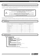
Delivery set ........................................................................................................................................................................................ 4
Designation key .............................................................................................................................................................................. 4
Technical data .................................................................................................................................................................................. 5
Unit design and operating principle ................................................................................................................................. 6
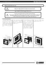
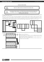
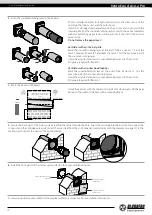
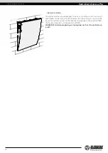
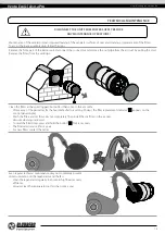
Installation and set-up................................................................................................................................................................ 8
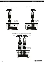
Connection to power mains and control ....................................................................................................................... 11
Technical maintenance .............................................................................................................................................................. 15
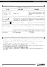
Troubleshooting ............................................................................................................................................................................. 16
Storage and transportation regulations .......................................................................................................................... 16
Manufacturer's warranty ........................................................................................................................................................... 17
Certificate of acceptance .......................................................................................................................................................... 19
Seller information .......................................................................................................................................................................... 19
Installation certificate .................................................................................................................................................................. 19
Warranty card ................................................................................................................................................................................... 19