


www.blaubergventilatoren.de
vento eco(2) a50-4 Pro
12
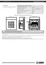
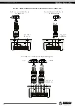
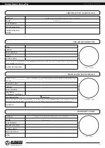
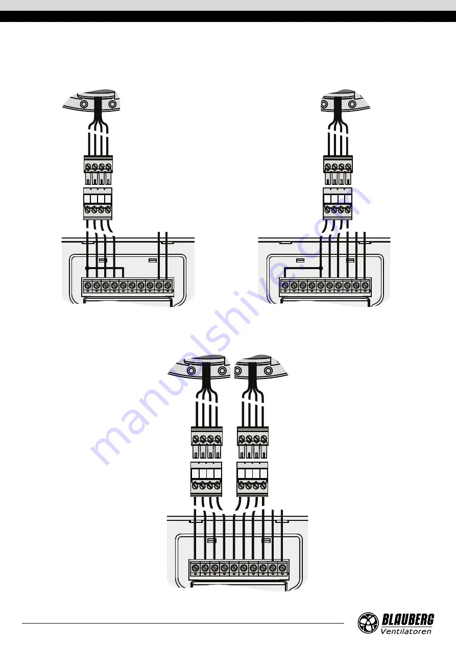
EXTERNAL CONNECTIONS WIRING DIAGRAM OF THE VENTILATOR WITH A CONTROL PANEL
Each unit is connected as an
air exhaust unit
Each unit is connected as an
air supply unit
100–240 V
50 (60) Hz
-
+
P1
T1
L
N
-
+
P2
T2
-
+
P2
T2
BLA
CK
RED
BL
UE
Y
ELL
OW
BLA
CK
RED
BL
UE
Y
ELL
OW
T P
+ -
100–240 V
50 (60) Hz
-
+
P1
T1
-
+
P1
T1
L
N
-
+
P2
T2
T P
+ -
BLA
CK
RED
BL
UE
Y
ELL
OW
BLA
CK
RED
BL
UE
Y
ELL
OW
100–240 V
50 (60) Hz
-
+
P1
T1
-
+
P1
T1
L
N
-
+
P2
T2
-
+
P2
T2
supply
Two units are connected to the control panel
extract
T P
+ -
T P
+ -