


www.blaubergventilatoren.de
Freshbox 110 (K1) (ErV)
9
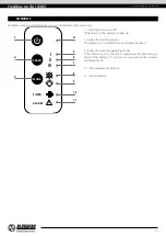
MOUNTING AND SET-UP
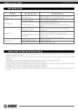
READ THE USER'S MANUAL BEFORE INSTALLING THE UNIT.
BEFORE INSTALLING ADDITIONAL ExTERNAL DEVICES,
READ THE RELEVANT USER MANUALS
Freshbox 110 (ERV)
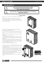
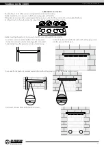
The delivery set includes a mounting template for marking the
holes.
Fix the mounting template at the required level on the wall.
Mark the holes for the air ducts and holes for mounting the unit.
Before installation operations route necessary cables and wires to
the unit mounting place.
Remove the mounting template and drill two through holes
Ø 120 mm in the wall for the air ducts.
When mounting the unit with an extract spigot prepare a hole in
the wall for a connecting bend and for laying of a rectangular air
duct.
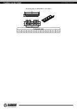
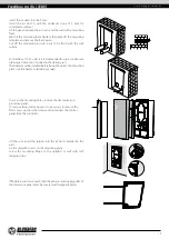
A connecting bend, rectangular and round air ducts are available
separately.
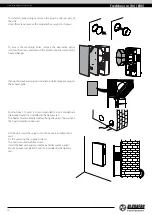
Drill Ø 8 mm holes to mount the unit.
Install the expansion anchors, remove the perforated fillers for the
air ducts from the mounting template and install the mounting
template back.
Prepare air ducts of required length. Note that the telescopic air
duct end must protrude for the distance that enables installation
of the outer ventilation hood. For details, refer to the installation
instruction for the ventilation hood.
The outer ventilation hood is available separately.
Insert the air ducts in the corresponding holes of the mounting
template. Install the air duct A with the minimum slope of 3 mm
for condensate removal.
To install the unit with an additional spigot, insert the connecting
bend into the prepared hole in the wall, aligning the mounting
template hole with a round end of the connecting bend. Connect
a rectangular duct to the connecting bend. Fill the gaps between
the air ducts and the wall with a mounting foam.
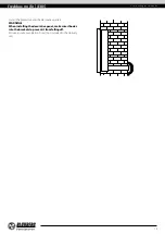
Wait till the mounting foam hardens then take off the mounting
template and remove the foam excess.
Cut off the protruding air duct parts to be flush with the wall
surface.
A
WHILE INSTALLING THE UNIT ENSURE CONVENIENT ACCESS FOR SUBSEQUENT
MAINTENANCE AND REPAIR.