


Freshbox 110 (K1) (ErV)
8
www.blaubergventilatoren.de
2
1
6
3
4
4
5
7
7
8
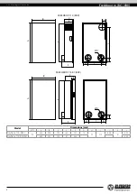
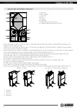
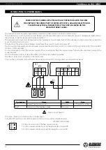
1: extract filter
2: heat exchanger
3: control unit
4: fan unit
5: drain pan
6: supply filter
7: damper with an electric actuator ()
8: condensate drain pipe (Freshbox 110 (K1))
Extract air from the room flows to the unit, where it is filtered by the extract filter, then air flows through the heat exchanger and is
exhausted outside by the extract fan.
Intake air from outside flows into the unit, where it is cleaned by the supply filter. Then filtered air flows through the heat exchanger
and is moved to the room with the supply fan.
Thermal energy of warm extract air is transferred to clean intake fresh air from outside and warms it up. The air flows are fully separated.
Heat recovery minimizes heat losses, which reduces the cost of space heating in the cold season.
Frost protection of the heat exchanger (danger of freezing appears when the exhaust air temperature downstream of the heat
exchanger is lower than +5 °C) is provided by automatically switching off the supply fan.
The frost protection mode of the heat exchanger is deactivated at an air temperature above +7 ˚С.
Frost protection is only possible in heat recovery mode.
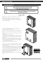
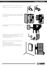
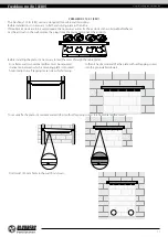
The Freshbox 110 (ERV) units provide for the installation of an exhaust spigot (Ø 100 mm) for servicing another room.
The spigot is included in the delivery set.
The exhaust grille must be covered with the magnetic plug supplied.
The Freshbox 110 K1 (ERV) units provide for the connection of FlexiVent 75 air ducts.
When using a mounting plate, the exhaust and supply grilles must be closed with the magnetic plugs included in the delivery set.
Freshbox 110 (ERV)
Freshbox 110 K1 (ERV) with mounting plate
1
1
3
3
2
2
4
4
1
1
3
3
2
4
4
1 – supply air
2 – intake air
3 – extract air
4 – exhaust air
DESIGN AND OPERATING PRINCIPLE