


Freshbox 110 (K1) (ErV)
14
www.blaubergventilatoren.de
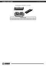
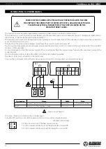
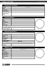
CONNECTION TO POWER MAINS
A1.1
XT4
X1
XT2
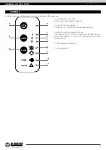
Boost
Boost*
PK1*
3 2 1
9 8 7 6 ... 1
Li Ni L N ... Ex
Fire
GND
Designation
Name
Cable
Note
PK1*
Contact from fire alarm panel
2x0.5 mm
2
Remove the jumper
Boost*
Contacts On/Off of the Boost mode
2x0.5 mm
2
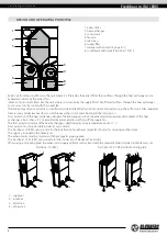
— Electric shock hazard!
The contact block J3 is located on the controller board.
Using the DIP switch, you can set the operation of the unit in summer ventilation mode
J3
1
1 2
3 4
DIP SWITCH POSITIONS
1-3: the unit works only in the heat recovery mode
1-2: in the summer ventilation mode, the exhaust fan is turned off
3-4: in the summer ventilation mode, the supply fan is turned off
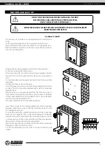
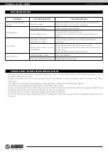
POWER OFF THE POWER SUPPLY PRIOR TO ANY OPERATIONS WITH THE UNIT.
THE UNIT MUST BE CONNECTED TO POWER SUPPLY BY A QUALIFIED ELECTRICIAN.
THE RATED ELECTRICAL PARAMETERS OF THE UNIT ARE GIVEN ON THE
MANUFACTURER’S LABEL.
The connection must be made using durable, insulated and heat-resistant conductors (cables, wires).
The actual wire cross section selection must be based on the maximum load current, maximum conductor temperature depending on
the wire type, insulation, length and installation method.
The external power input must be equipped with an automatic circuit breaker built into the stationary wiring to open the circuit in the
event of overload or short-circuit.
The position of the external circuit breaker must ensure free access for quick unit power-off.
The trip current of the automatic circuit breaker must exceed the maximum current consumption of the unit (refer to the “Technical data”
section or to the unit label).
It is recommended to select the nominal current of the circuit breaker from the standard series, following the maximum current of the
connected unit.
The circuit breaker is not included in the delivery set and can be ordered separately.
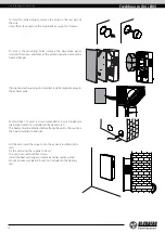
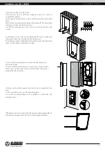
The device contacts are connected in the control unit.
To access the control unit, remove the decorative panel, unscrew the screws and remove the protective panel.