background image


BladeZ Corporation  •  20155 Ellipse  •  Foothill Ranch  •  CA  •  92610 

www.ebladez.com

  •  Phone 949-206-8152  •  Fax 949-206-0013 

8

ASSEMBLY INSTRUCTIONS CONTINUED 


3.  Slide the Necklace Bracket (#18) from the 

upper Upright & Rocker (#2) and then insert 
the Computer Shelf (#10) into Upright & 
Rocker. First insert Bolt (#69), Washer (#70, 
77), leave them finger tight until all are in 
place, and then tighten them with the 
Wrench.


4.  Smear Lubricant (#165) onto the 

spacer in the axis of Frame (#1) and 
Pedal Assembly (#5, 6). Attach the 
rear Pedal Assembly to Frame with 
Bolt (#38), Washers (#77, 17), 
Bushing (#39) then cap the Screw 
Cover (#37). 


Summary of Contents for ION 490E

Page 1: ...BladeZ Corporation 20155 Ellipse Foothill Ranch CA 92610 www ebladez com ION 490E OWNER S MANUAL 20155 Ellipse Foothill Ranch CA 92610 Phone 949 206 8152 Fax 949 206 0013 Revised 11 01 06...

Page 2: ...ffective and enjoyable Please read this manual carefully before using your 490E elliptical This will allow you to gain a full understanding of all the features BLADEZ elliptical provide If you have an...

Page 3: ...llipse Foothill Ranch CA 92610 www ebladez com Phone 949 206 8152 Fax 949 206 0013 2 TABLE OF CONTENTS SECTION PAGE 1 IMPORTANT SAFETY INSTRUCTIONS 3 2 ASSEMBLY INSTRUCTIONS 5 3 GETTING STARTED 12 4 O...

Page 4: ...unplug the elliptical prior to cleaning to reduce the risk of electric shock serious burns and the risk of injuries 7 The elliptical should never be left unattended when in operation Unplug the ellipt...

Page 5: ...power supply for use on a nominal 110 120 volt circuit Use only the power supply provided with your ION 490E Elliptical If you misplace this power supply please contact Bladez for an original replace...

Page 6: ...Frame 1 2 Upright Rocker 1 4 Hand Pulse Sensor 1 5 Pedal Assembly L 1 6 Pedal Assembly R 1 8 Handrail 2 10 Computer Shelf 1 11 Computer 1 18 Necklace Bracket 1 31 Pedal Cover B 2 32 Pedal Cover A 2 3...

Page 7: ...2T Washer 2 38 Bolt M8 x 20 2 39 Bushing 2 69 Bolt M8 x 15 11 70 Arc Washer 11 71 Screw M4 x 10 2 77 M8 x 2T Spring Washer 13 88 Lug Wrench SEG1317 2 89 Screwdriver 1 122 Screw M8 x 56 4 125 M8 Acorn...

Page 8: ...7 with Bolt 122 Washers 136 137 and Acorn Nut 125 2 Connect the upper Control Wire to the lower one Push up the Upper Front Cover 68 along the Upright Rocker 2 lift the Upright Rocker and insert it in...

Page 9: ...er Upright Rocker 2 and then insert the Computer Shelf 10 into Upright Rocker First insert Bolt 69 Washer 70 77 leave them finger tight until all are in place and then tighten them with the Wrench 4 S...

Page 10: ...13 9 ASSEMBLY INSTRUCTIONS CONTINUED 5 Smear the Lubricant 165 onto the bearing of the Upright Rocker 2 Secure the front Pedal Assembly 5 6 and Upright Rocker with Bolt 159 Nylon Nut 160 Finally assem...

Page 11: ...uter 11 Attach the Computer to the Computer Shelf 10 with four Screws 152 Push up the Necklace Bracket 18 over the back of the Computer and secure with two Screws 71 Attach the Hand Pulse Sensors 4 to...

Page 12: ...STRUCTIONS CONTINUED 9 Refer to the drawing to the right Unscrew the Bolt 183 from the Upright Rocker 2 attach the Bottle Holder 182 to the Upright Rocker 2 with Screw 183 then insert the Bottle 181 i...

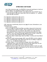
Page 13: ...ess to confirm START STOP Press to start pause or stop Key Press to select during edit and increase the WATT level under RUN status when the WATT is 400 press again and the WATT level will go to 0 Key...

Page 14: ...displaying NOTE The pulse signal has 2 forms input by the handgrip pulse sensor or transmitted by the wireless pulse transmitter The wireless pulse transmitter is only intended for the products that...

Page 15: ...e is displayed press ENTER to edit the detailed functions 4 After the function is set press START to enter RUN mode 5 In RUN mode if you press STOP then you will enter Pause mode if you hold STOP for...

Page 16: ...Press or to adjust the WATT level At this time the ENERGY window will display the adjusted WATT level and then switch back to the Kcal number display after several seconds Program P 1 1 This program h...

Page 17: ...nd the intensity of exercise before using this function When you enter RUN mode the unit will compare the user s current heart rate with the max value and then adjust the WATT level to keep the user s...

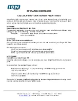
Page 18: ...220 30 190BPM STEP TWO Select your ideal workout HR Zone Once you have your maximum heart rate you can use it to determine your Target HR Zone based on your fitness goal s Recent studies have shown 60...

Page 19: ...of the console Then press PULSE Recovery key After you press the PULSE Recovery key the matrix window will display Rec and then count down for one minute If there is no heart rate signal input the mat...

Page 20: ...date of original purchase as long as the device remains in the possession of the original owner EXCLUSIVE REMEDY The exclusive remedy for any of the above warranties shall be repair or replacement of...

Reviews: