background image

7

EN

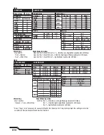
Servo Setup

FUNCTION LIST

SYSTEM SETUP

DX8

SYSTEM SETUP

Model Type

Airplane

F-Mode Setup

Switch 1

Switch B

Switch 2

Inhibit

Channel Assign

Channel Input

1 Throttle

N/A

2 Aileron

N/A

3 Elevator

N/A

4 Rudder

N/A

5 Gear

B

6 AUX 1

I

Chan

Travel

Reverse

THR

100/100

Normal

AIL

100/100

Normal

ELE

100/100

Normal

RUD

100/100

Normal

GER

100/100

Normal

Chan

Travel

Reverse

AX1

100/100

Reverse

AX2

100/100

Normal

AX3

100/100

Normal

AX4

100/100

Normal

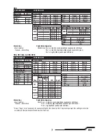
Servo Setup

FUNCTION LIST

DX6, DX7 (Gen 2), DX9, DX18

Timer

Mode

Count Down

Time

5:00

Start

Throttle Out

Over

25%

One Time

Inhibit

D/R & Expo

Chan

Switch (F) Pos

D/R

Expo*

DX6

DX7, 9, 

18

AILE

0

0

100/100

0

1

100/100

0

1

2

75/75

0

ELEV

0

0

100/100

0

1

100/100

0

1

2

75/75

0

RUDD

0

0

100/100

0

1

100/100

0

1

2

75/75

0

D/R & Expo

Chan

Switch Pos (AIL D/R)

D/R

Expo*

AILE

0

100/100

0

1

100/100

0

2

75/75

0

ELEV

0

100/100

0

1

100/100

0

2

75/75

0

D/R & Expo

Chan

Switch Pos (AIL D/R)

D/R

Expo*

RUDD

0

100/100

0

1

100/100

0

2

75/75

0

Timer
Mode

Count Down

Time

5:00 Tone

Start

Throttle Out

Pos

25%

Chan

Travel

Reverse

THR

100/100

Normal

AIL

100/100

Normal

ELE

100/100

Normal

RUD

100/100

Normal

Chan

Travel

Reverse

GER

100/100

Normal

AX1

100/100

Reverse

AX2

100/100

Normal

Model Type

ACRO

SW Select

Trainer

Aux 1

F Mode

Gear

All Others

INH

Motor Stop

Bind / I Button

Pressed = Motor Stop

Motor Stop

Bind / I Button

Pressed = Motor Stop

*  

Use of "Expo" is not necessary for successful fl ight of the Inductrix 200. The pilot may adjust this setting to tailor the
sensitivity of the quadcopter around neutral if desired.

Flight Mode Operation

F MODE Sw:  

Pos 0 = Stability, Low-Angle Mode (quadcopter LED Blue)
Pos 1 = Stability, High-Angle Mode (quadcopter LED Green)
Pos 2 = Agility Mode (quadcopter LED Red)

Flight Mode Operation

Sw B:  

Pos 0 = Stability, Low-Angle Mode (quadcopter LED Blue)
Pos 1 = Stability, High-Angle Mode (quadcopter LED Green)
Pos 2 = Agility Mode (quadcopter LED Red)

Summary of Contents for InducTrix 200

Page 1: ...Instruction Manual Bedienungsanleitung Manuel d utilisation Manuale di Istruzioni ...

Page 2: ... keep a safe distance in all directions around your model to avoid collisions or injury This model is controlled by a radio signal subject to interference from many sources outside your control Interference can cause momentary loss of control Always operate your model in open spaces away from full size vehicles traffic and people Always carefully follow the directions and warnings for this and any ...

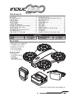
Page 3: ...tion 4 Flying Checklist 4 Charging Warnings 4 Battery Charging 4 Transmitter Setup 5 Installing the Flight Battery 8 Powering On the Inductrix 200 Quadcopter 8 Transmitter and Receiver Binding 8 SAFE Technology 9 Understanding the Primary Flight Controls 9 Flight Mode Selection 10 Flying the Inductrix Quadcopter 10 Using the Micro Camera 11 Post Flight Inspection and Maintenance Checklist 11 Repla...

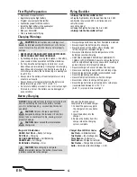
Page 4: ...s Charge current error Five Flashes Charge time protection Solid Hardware protection Voltage 4 3V CAUTION All instructions and warnings must be followed exactly Mishandling of Li Po batter ies can result in a fire personal injury and or property damage NEVER LEAVE CHARGING BATTERIES UNATTENDED NEVER CHARGE BATTERIES OVERNIGHT By handling charging or using the included Li Po battery you assume all r...

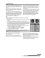
Page 5: ...ch Motor Stop is controlled by the Bind Panic Trainer button Once bound the LED in the quadcopter should glow blue for flight mode 0 Stability low angle mode green for flight mode 1 Stability high angle mode and red for flight mode 2 Agility mode If the motors will not start when giving the correct start command channel 6 has not been reversed correctly Use the directions above to reverse channel 6 T...

Page 6: ...ired D R Expo Chan Sw Pos D R Expo AILE 0 100 INH 1 75 INH ELEV 0 100 INH 1 75 INH RUDD 0 100 INH 1 75 INH Timer Down Timer 5 00 Switch THR CUT ADJUST LIST SETUP LIST DX6i TRAVEL ADJ Channel Travel THRO 100 100 AILE 100 100 ELEV 100 100 RUDD 100 100 GEAR 100 100 FLAP 100 100 REVERSE Channel Direction THRO N AILE N ELEV N RUDD N GEAR R FLAP N Modulation Type AUTO DSMX ENABLE D R COMBI D R SW AILE M...

Page 7: ... ELEV 0 100 100 0 1 100 100 0 2 75 75 0 D R Expo Chan Switch Pos AIL D R D R Expo RUDD 0 100 100 0 1 100 100 0 2 75 75 0 Timer Mode Count Down Time 5 00 Tone Start Throttle Out Pos 25 Chan Travel Reverse THR 100 100 Normal AIL 100 100 Normal ELE 100 100 Normal RUD 100 100 Normal Chan Travel Reverse GER 100 100 Normal AX1 100 100 Reverse AX2 100 100 Normal Model Type ACRO SW Select Trainer Aux 1 F ...

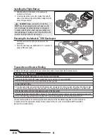
Page 8: ... instructions and refer to the troubleshooting guide for other instructions If needed contact the appropriate Horizon Product Support office For a list of compatible DSM transmitters please visit www bindnfly com Transmitter and Receiver Binding General Binding Procedure 1 Refer the Transmitter Setup Table to correctly setup your transmitter 2 Lower the throttle stick to the lowest position and cent...

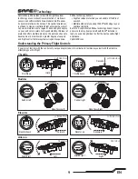
Page 9: ...envelope protection you can enable at the flip of a switch Multiple modes let you adapt SAFE technology to your skill level instantly Best of all sophisticated SAFE technology doesn t require any work to enjoy Every aircraft with SAFE installed is ready to use and optimized to offer the best possible flight experience FlySAFERC com Technology Elevator Forward Elevator down Elevator up Backward Left ...

Page 10: ...site direction to stop the movement Do not use the trims on the transmitter to eliminate drift If the quadcopter does not hold a reasonable hover in calm conditions perform the Drift Calibration Flying With your quadcopter maintaining a stable low level hover practice using the rudder elevator and aileron controls to familiarize yourself with the machine s responses to control inputs Remember to k...

Page 11: ...ings The range of the system can be impacted by any obstructions blocking your signal It is normal to see break up in the video going behind trees and other obstacles Ultra Micro FPV Camera Transmitter Channels Channel 1 5740 MHz Channel 2 5760 MHz Channel 3 5780 MHz Channel 4 5800 MHz Channel 5 5820 MHz Channel 6 5840 MHz Channel 7 5860 MHz Using the Micro FPV Camera These frequencies are compati...

Page 12: ... to position 0 4 Start the motors normally 5 Slowly advance the throttle to bring the quadcopter into a low hover The LED will flash continuosly to indicate the calibration process has begun Hold the hover for approximately 15 seconds using as little control input as possible to keep the quadcopter steady 6 Land the quadcopter by slowly lowering the throttle 7 After landing press the bind panic but...

Page 13: ... is too close to large metal object wireless source or another transmitter Move quadcopter and transmitter to another location and attempt binding again Difficulty connecting after binding Less than a 5 second wait between first powering on the transmitter and powering on the quadcopter Leave the transmitter powered on Power off the quadcopter and power it back on The quadcopter is bound to a differ...

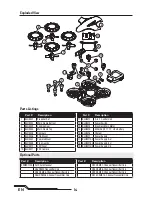
Page 14: ... Channel Transmitter Only Optional Parts Part Description 1 BLH9001 Propeller Set 2 BLH9002 Main Frame Bottom 3 BLH9003 Landing Gear 4 BLH9004 Main Frame Top 5 BLH9005 Dampers 6 BLH9006 PCB Mount 7 BLH9007 Camera Mount 8 BLH9008 Prop Guards 9 BLH9010 LED Cover 10 BLH9011 FPV Camera Part Description 11 BLH9012 3 in 1 Control Unit 12 BLH9013 Power Switch 13 BLH9014 Brushless Main Motor 14 BLH9015 80...

Page 15: ...you in the event that you may need any assistance For questions or assistance please visit our website at www horizonhobby com submit a Product Support Inquiry or call the toll free telephone number refer enced in the Warranty and Service Contact Information section to speak with a Product Support representative Inspection or Services If this Product needs to be inspected or serviced and is compli...

Page 16: ... Instead it is the user s responsibility to dispose of their waste equipment by handing it over to a designated collections point for the recycling of waste electrical and electronic equipment The separate collection and recycling of your waste equipment at the time of disposal will help to conserve natural resources and make sure that it is recycled in a manner that protects human health and the ...

Page 17: ...are ModelMatch and the Horizon Hobby logo are trademarks or registered trademarks of Horizon Hobby LLC The Spektrum trademark is used with permission of Bachmann Industries Inc All other trademarks service marks or logos are property of their respective owners Patents pending Created 1 16 51869 BLH9080 ...

Reviews: