201A-A00 Page 5/12
OPERATION
DIRECT ACTING RELIEF VALVE
NOTICE:
The direct acting relief valve is designed to protect the
pump from excessive pressure and must not be used as
a system pressure control valve.
Pumping volatile liquids under suction lift may cause
cavitation.
DO NOT
partially close the discharge valve. This
WILL
result in internal relief valve chatter. For these
applications, install an external bypass valve, and any
necessary piping, back to the storage tank. Use a bypass
system when operating for extended periods (more than 1
minute) against a closed discharge valve.
RELIEF VALVE SETTING AND ADJUSTMENT
Hazardous machinery
can cause serious
personal injury or
death.
Failure to disengage PTO before
adjusting pump relief valve can cause
severe personal injury or death.
Hazardous pressure
can cause serious
personal injury or
property damage.
Incorrect settings of the pressure relief
valve can cause pump component
failure, personal injury, and property
damage.
Hazardous or toxic
fluids can cause
serious injury.
Relief valve cap is exposed to pumpage
and will contain some fluid
The relief valve pressure setting is marked on a metal tag
attached to the valve cover. Generally, the relief valve should
be set at least 15 -20 psi (1.0 - 1.4 Bar) higher than the
operating pressure, or the external bypass valve setting
(if equipped).
DO NOT remove the R /V Cap OR adjust the relief valve
pressure setting while the pump is in operation.
1.
To INCREASE the pressure setting,
remove the relief
valve cap, loosen the locknut, and turn the adjusting screw
inwar
d, or clockwise. Replace the valve cap.
2.
To DECREASE the pressure settin
g, remove the relief
valve cap, loosen the locknut, and turn the adjusting screw
outwar
d, or counterclockwise. Replace the valve cap.
Refer to the individual Blackmer pump parts lists for various
spring pressure ranges. Unless specified otherwise, pumps
are supplied from the factory with the relief valve adjusted to
the mid-point of the spring range.
OPTIONAL PNEUMATIC RELIEF VALVE
The optional pneumatic actuated relief valve is designed to
operate at two different relief pressures. The
High Pressure
mode provides pressure for product delivery. The Low
Pressure mode allows the pump to bypass fluid at lower
pressure during no flow conditions. Flow sense products are
available from other manufacturers. When air pressure is
applied, the pneumatic valve achieves the maximum pressure
setting to allow the full liquid flow through the system.
The pneumatic relief valve can be supplied with either a low
pressure or a high pressure spring:
The
low pressure spring
(8A) will bypass at 75 psi (5.2
bar) in actuated mode, and 40 psi (2.8 bar) full flow in
non-actuated mode. The low pressure spring requires
60 psi (4.1 bar) minimum air pressure to activate.
The
high pressure spring
(8B) will bypass at 115 psi
(7.9 bar) in actuated mode, and 55 psi (3.8 bar) full flow
in non-actuated mode. The high pressure spring
requires a minimum of 95 psi (6.6 bar) air pressure to
activate.
The pneumatic relief valve is controlled by a three-way valve
piped to vent the pneumatic valve to atmosphere when in the
OFF position. The breather (10B) in the cover is designed to
function as a “tell-tale” to indicate any seal problems with the
actuating piston.
NOTICE:
If any fluid or air flow appears at the breather (10B), the
seals (9D or 9F) are leaking and MUST be REPLACED
immediately.
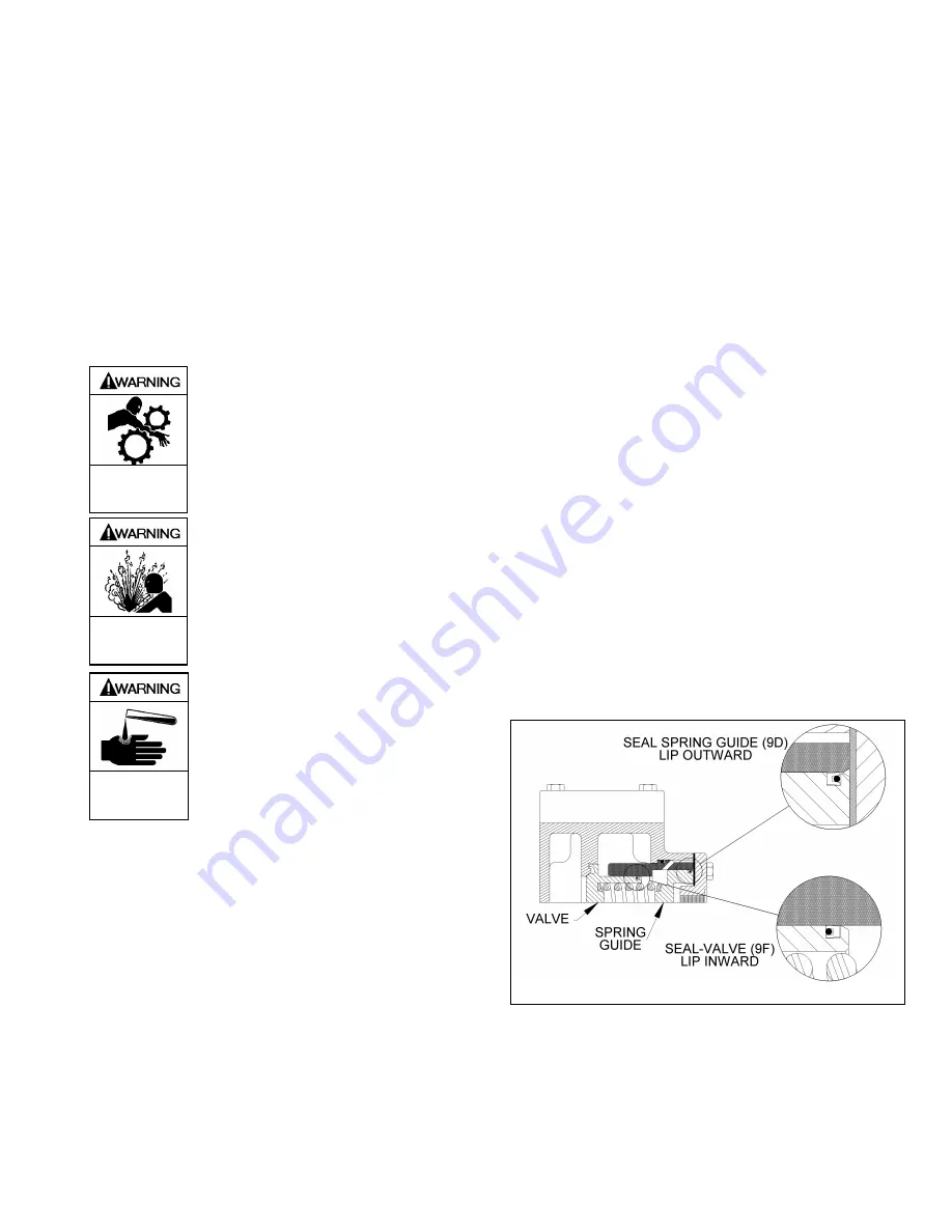
When replacing the pneumatic relief valve seals (9D and 9F),
it is important that they be positioned properly, as shown in
Figure 2.
Figure 2 – Optional Pneumatic Relief Valve
Summary of Contents for ATX300A
Page 11: ...201A A00 Page 11 12 NOTES...


