201A-A00 Page 3/12
INSTALLATION
NOTICE:
Blackmer truck pumps must only be installed in systems
designed by qualified engineering personnel. System
design must conform with all applicable regulations and
codes and provide warning of all system hazards.
PRE-INSTALLATION CLEANING
NOTICE:
New pumps contain residual test fluid and rust inhibitor.
If necessary, flush pump prior to use.
Foreign matter entering the pump WILL cause extensive
damage. The supply tank and piping MUST be cleaned and
flushed prior to pump installation and operation.
LOCATION AND PIPING
An improperly designed piping system or unit installation
WILL significantly reduce pump performance and life. The
following are piping system guidelines for pump installation.
1. To minimize intake losses, locate the pump as close as
possible to the source of supply.
2. Piping MUST be properly supported to prevent any piping
loads from being placed on the pump.
3. Intake piping and fittings MUST be at least as large in
diameter as the pump intake connection.
4. Minimize the number of intake line fittings (valves, elbows,
etc.) and piping turns or bends.
5. Install vacuum and pressure gauges in the ¼" NPT ports
located on the pump cylinder near the intake and
discharge flanges to check pump at start-up
6. Install a strainer in the inlet line to protect the pump from
foreign matter. Place the intake strainer to allow frequent
cleaning.
7. Intake and discharge piping MUST be free of all leaks.
TRUCK MOUNTING
The pump will operate satisfactorily in any position. Consult
Blackmer factory for vertical shaft mounts. The pump can be
bolted to the truck frame or on a saddle hung below the
frame, and MUST be adequately supported.
PUMP DRIVE
The pump may be driven by a power take-off through
universal joints. When using universal joints, a splined slip
joint, properly lubricated, must be used on the connecting
jackshaft to prevent end thrust on the pump shaft.
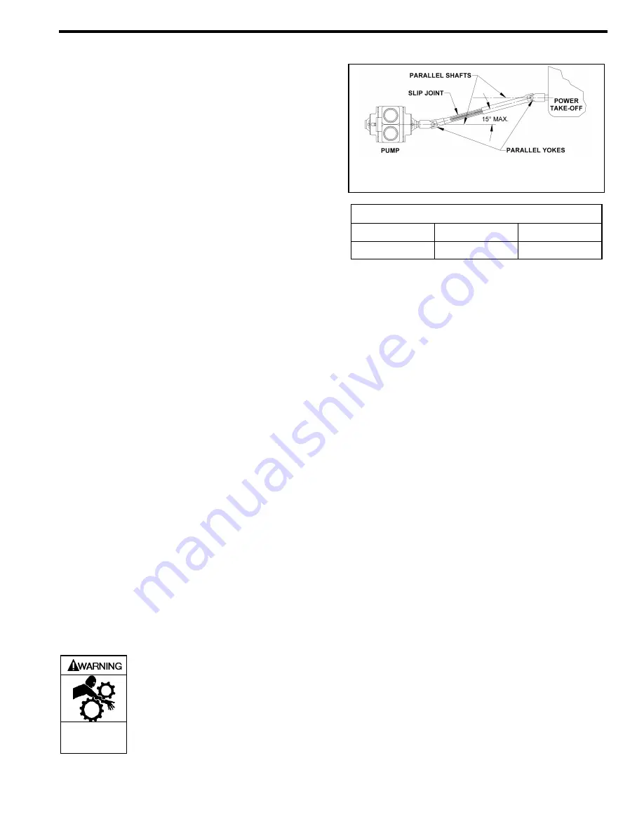
It is very important to install a proper drive line to avoid
excessive wear, vibration and noise. See Fig. 1 and Table 1.
Do not operate
without guard
in place.
A drive shaft guard between the PTO
and pump must be provided to prevent
personal injury, property damage, or
death.
Note: A Drive Shaft Guard between the pump and the
PTO MUST be provided. (Not Shown)
Figure 1 Pump Drive
Angle of Drive Shaft
1º through 5º
6º through 10º
11º through 15º
Very Good
Good
Fair
Table 1
General guidelines to follow for proper pump drive:
1. DO NOT use Square slip joints.
2. Use the least number of jackshafts as is practical.
3. Use an even number of universal joints.
4. The pump shaft and power take-off shaft must be parallel
in all respects. Use an angular level measuring device to
ensure the PTO and pump shafts are parallel to each
other. If necessary, the pump can be shimmed to correct
any misalignment. The PTO shaft coming off at the
transmission does not need to be perfectly horizontal as
long as the pump is shimmed to have its shaft parallel in
all respects to the PTO shaft.
5. The yokes of the universals at both ends of the jackshaft
must be parallel and in phase.
6. The maximum angle between the jackshaft and the pump
shaft is 15 degrees. Refer to Table 1.
Failure to follow any of these guidelines may result in a gallop
or uneven turning of the pump rotor, which will in turn cause a
surging vibration to the liquid stream and piping system.
Contact the supplier of the drive line components for specific
design assistance.
HYDRAULIC DRIVE
The ATX300A-HYD models are driven hydraulically.
Hydraulic motors should be well supported with their shafts
parallel to the pump shaft in all respects. ATX-HYD models
are equipped with a close-coupled hydraulic motor adapter
that provides for straight alignment of a hydraulic motor drive
through a solid coupling connected to a splined pump shaft.
This coupling connection requires grease lubrication every
three months at
minimum.
Refer to the "Lubrication" section
of this manual.
PUMP ROTATION
NOTICE:
Confirm correct pump rotation by checking the pump
rotation arrows respective to pump driver rotation.
TO CHANGE PUMP ROTATION
To reverse rotation, the pump must be disassembled then
reassembled with the shaft on the opposite side of the pump.
See the ‘Maintenance’ section for instructions.
Summary of Contents for ATX300A
Page 11: ...201A A00 Page 11 12 NOTES...


