111-F00 Page 12/16
MAINTENANCE:
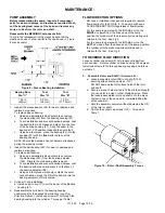
15. LOCKNUT ADJUSTMENT
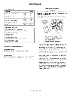
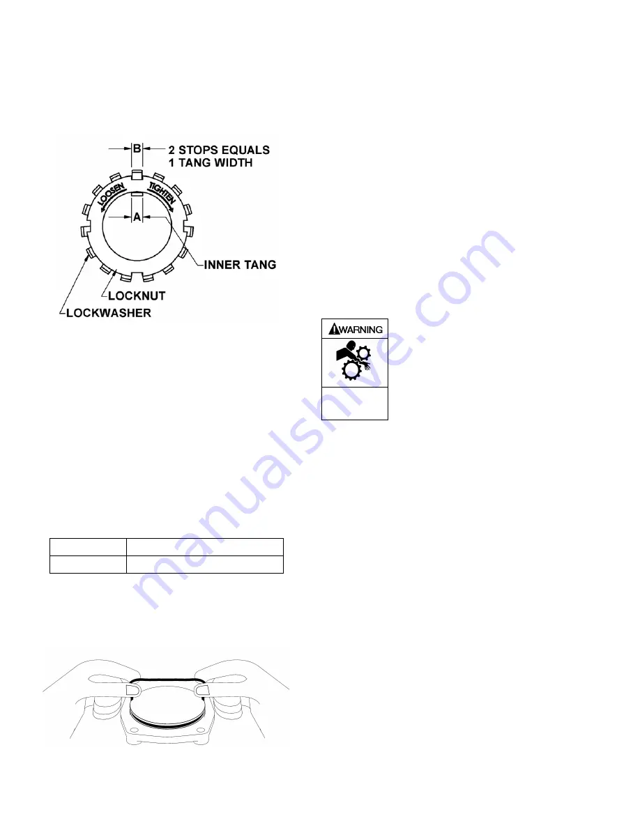
It is important that the bearing locknut (24A) and lock
washer (24B) be installed and adjusted properly. Over
tightening the locknut can cause bearing failure or a
broken lock washer tang. A loose locknut will allow the
rotor to shift within the pump, causing wear.
See Figure 12.
Figure 12 – Locknut Assembly
a. On the end of the pump shaft, install a lock washer
(24B) with the tangs facing outward, followed by a
locknut (24A) with the tapered end inward. Ensure the
inner tang "A" of the lock washer is located in the slot
in the shaft threads, bending it slightly, if necessary.
b. Tighten the locknut to ensure that the bearing is
bottomed in the recess. DO NOT over tighten and
bend or shear the lock washer inner tang.
Bearing Adjustment
16. Turn the bearing adjuster counterclockwise, as viewed
from the driven end of the pump, until the shaft is snug
and no longer turns. Mark a line across the bearing
adjuster and drive housing.
17. Turn the bearing adjuster clockwise, as viewed from the
driven end of the pump the distance prescribed per table
2. Measurement to be taken on outside of drive housing.
Table 2
Pump size
Distance on OD of Drive Housing
PV(S) 6,8
3/4” (19.05 mm)
18. Tighten the bearing adjuster lock setscrews and torque
per table 1.
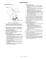
19. Install a new head O-ring (72) on the dowel of the head
as shown in Figure 13.
Figure 13 – Head O-ring Installation
20.
Carefully install the head (23) into the cylinder.
If pump
is equipped with internal relief valve, orient the relief
valve per instruction in PUMP RELIEF VALVE section
of this manual.
Install and tighten four head cap screws
(21A). Torque per table 1.
21. RELIEF VALVE ASSEMBLY
a. Insert the valve into the valve body with the fluted in
inward.
b. Install the relief valve spring onto valve and spring
guide onto spring.
c. Screw the adjusting screw into the valve cover until it
makes contact with the spring guide
d. Install the relief valve cap and o-ring after the relief
valve has been properly adjusted.
NOTICE:
The relief valve setting MUST be tested and adjusted
more precisely before putting the pump into service.
Refer to “Relief Valve Setting and Adjustment”.
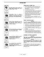
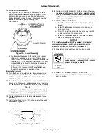
22. Reinstall coupling, shaft key, and coupling guards.
Do not operate
without guard
in place
Operation without guards in place can
cause serious personal injury, major
property damage, or death.
23. Refer to “Pre-Startup Check List” and “Startup
Procedures” sections of this manual prior to restarting
pump operation.
Summary of Contents for 111-F01
Page 15: ...111 F00 Page 15 16 NOTES...


