background image


Version 2020-5.0_ENG 
 

 56 

5.3


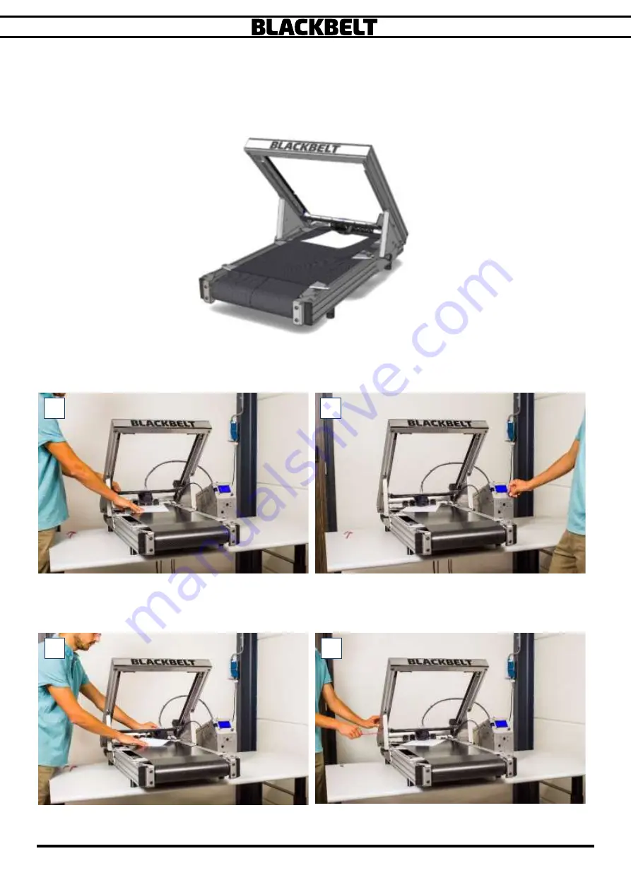
Calibration Y axis


You’ll need a 5

mm and 3mm 

Hexagon

 key and a sheet of paper 

5.


Set the gantry to 45° and mount a printhead. 

6.


Take a piece of paper, put it on the conveyor belt and place the printhead onto it: 


7.


Turn the printer on, press the jog wheel, select by rotating and pressing 
Prepare 

 Move axis 

 Move  Y 

 Move 0.1mm 


8.


Turn the jog wheel to the right until you can move the paper freely 

9.


Now carefully move the printhead by hand to the left and right side, while constantly checking with the 
piece of paper if you can still move it freely. Do not move any further when you notice a resistance. [3] 


10.


If you start noticing a resistant at one side, move the printhead to the opposite side. 

11.


Loosen the following 3 screws for ½ rotation at one side of your choice, using the 5mm Hexagon key: 

Summary of Contents for Blackbelt

Page 1: ...Installation User Manual Bowden varioDrive Original document Version 2020 5 0 ...

Page 2: ...Version 2020 5 0_ENG 1 Intentionally left blank ...

Page 3: ...inter The conditions or methods used for assembling handling storage use or disposal of the device are beyond our control and may be beyond our knowledge For this and other reasons we do not assume responsibility and expressly disclaim liability for loss injuries damage or expense arising out of or in any way connected with the assembly handling storage use or disposal of the product The informati...

Page 4: ...Version 2020 5 0_ENG 3 Intentionally left blank ...

Page 5: ...ndings Environment 19 3 4 Assembly installation and commissioning the machine 19 3 4 1 Positioning 19 3 4 2 Assembly wiring 19 3 4 3 Setting up the 3D printer 20 3 4 4 Installation of the printhead BOWDEN 21 3 4 5 Installation of the printhead varioDrive 23 3 5 Operating the BlackBelt 3D platform 27 3 5 1 Loading filament 27 3 5 2 Material change BOWDEN 28 3 5 3 Material change varioDRIVE 29 3 5 4...

Page 6: ...ditional hardware 72 6 1 BlackBelt Server 73 6 1 1 Webcam mount 75 6 1 2 Software setup 76 6 1 3 File upload 79 6 1 4 Print queue 80 6 1 5 Timelapse 81 6 1 6 Adding multiple users 82 6 1 7 Control 83 6 1 8 Webcam settings 84 6 1 9 Terminal 85 6 1 10 Possible failure mode 85 6 3 Run out sensor 86 6 3 1 Retrofit installation 86 6 4 Using the run out sensor 87 6 5 varioDrive retro fit package 88 6 5 ...

Page 7: ...ure 102 7 3 BlackBelt PCB 104 7 3 1 BlackBelt PCB v1 4 104 7 3 2 BlackBelt PCB v1 4 varioDrive 105 7 3 3 BlackBelt PCB v1 3 106 7 4 Possible failure mode 107 7 5 Disposing the machine or machine parts 108 7 6 EG declaration of compliance 12 ...

Page 8: ...Version 2020 5 0_ENG 7 Intentionally left blank ...

Page 9: ...Version 2020 5 0_ENG 8 1 Safety and compliance ...

Page 10: ...ur website www blackbelt 3d com Do not use of the machine for any other purposes then intended by BlackBelt 3D BV Not doing so can lead to serious damage to the machine or the machine operator and its surroundings The Blackbelt 3D printer generates high temperatures and has hot moving parts that can cause injury Never reach inside of Blackbelt 3D Printer while it is in operation Always control the...

Page 11: ... As long as the machine is in use and switched on no connector or safety precautions shall be removed Only use the machine if all safety precautions are installed and ready for use 7 Prescribed service intervals and maintenance instructions as mentioned in this user manual must be maintained at all times 8 Only allow qualified personnel to replace spare parts and carry out maintenance and repairs ...

Page 12: ...calibrate and fine tune the machine and modify fixed parameters No users may change or temporarily overrule or disengage safety features 1 4 Transportation Please follow all prescriptions as described in this manual In particular chapter 1 3 Safety messages The transportation box of the Blackbelt 3D Printer must carried out horizontally The humidity in the cardboard packaging must not be allowed t...

Page 13: ...he provisions of the EMC directive 2014 30 EG complies with harmonized European standards Harmonised European standard Description Harmonised European standard Description NEN EN ISO 12100 2010 Safety of machinery General principles for design part 1 Basic principles methodology NPR ISO TR 14121 2 2010 Safety of machinery Risk assessment Part 2 Practical guidance and examples of methods NEN EN IEC...

Page 14: ...Version 2020 5 0_ENG 13 Intentionally left blank ...

Page 15: ...Version 2020 5 0_ENG 14 2 Introduction ...

Page 16: ...s 2 1 2 Bowden This is the so called standard setup and works good with all the recommended rigid materials You can recognize this setup at the printhead In the images below You see an example of the standard 0 4 printhead 1 and hardened steel 0 4 printhead 2 for fiber filled materials Or materials that are very abrasive due to added particles as steel bronze ceramics etc 2 1 3 varioDrive The vari...

Page 17: ... Z Axis cold segment 3 Angle Adjusting knob 4 Conveyor belt Z Axis heated segment 5 Cooling fan 6 X Axis 7 Y Axis 2x 8 Printhead assembly 9 SD Card Slot 10 Display 11 Menu jog wheel 12 Electrical control cabinet 13 Filament inlet entry 14 USB Port 15 Filament spool holder 3 1 2 4 5 8 9 13 30 14 15 10 12 30 11 30 6 7 ...

Page 18: ... Control panel front side Electrical cabinet backside X motor connector red Y motor connector green Power main Fuse Main Switch SD Card slot Display Menu jog button Filament entrance USB port entrance Connector Heatbed Filament Insert lever Z motor connector blue ...

Page 19: ...Version 2020 5 0_ENG 18 3 Installation ...

Page 20: ...u ll also need a computer using Windows or Mac iOS operating system 3 3 Surroundings Environment Set up the printer on a stable table in a dry and clean room with a temperature between 15 35 C The minimal dimensions of the table should be 80cm x 80cm 3 4 Assembly installation and commissioning the machine Please follow all prescriptions as described in this manual In particular chapter 1 3 Safety ...

Page 21: ... 5 Connect the cables wires of the 3D printer with the connectors on the control cabinet 1 The connector with the red indicator connects with the contact labeled X Motor 2 The connector with the green indicator connects with the contact labeled Y Motor 3 The connector with the blue indicator connects with the contact labeled Z Motor 4 The bigger connector without an indicator connects with the con...

Page 22: ...2 Position the 2 printhead screws in the printhead assembly and position the printhead in front of the cooling fan assembly 3 Move the X and Y axis of the printer to the middle of the XY gantry providing access to the backside of the X axis 4 Assemble the printhead on the X axis The screws can be inserted in the 2 holes of the linear sled of the X axis 5 Connect the wires tubes of the control cabi...

Page 23: ...together with the printhead Pull the cable and release the fan from the assembly 2 4 Detach the spring tube and cables 3 5 Move the X and Y axis of the printer to the middle of the XY gantry providing access to the backside of the X axis 4 6 Assemble the printhead on the X axis The screws can be inserted in the 2 holes of the linear sled of the X axis 5 7 Connect the wires tubes onto the printhead...

Page 24: ...m all sides Parts needed to install the printhead 3D printer assembled as described in chapter 2 varioDrive Printhead with Printhead screws Hexagon key 3mm Indicator Nozzle diameter 0 4mm Entry holes Screws printhead Contact motor cable PTFE Tube entry Spiral cable entry Printhead screws Contact control cabinet Heater cable connector Temperature sensor connector Fan cable connector ...

Page 25: ...nd Y axis of the printer to the middle of the XY gantry providing access to the backside of the X axis Make sure the current bolts are configured as shown above each other 2 4 Assemble the printhead on the X axis The screws can be inserted in the 2 holes of the linear sled of the X axis 3 5 Connect the wires tubes of the control cabinet with the print head 4 a First the spiral cable spring into th...

Page 26: ...s 1 2 10 Move the X and Y axis of the printer to the middle of the XY gantry providing access to the backside of the X axis Disconnect all the cables and Bowden 1 11 Unscrew the two bolts that attach the printhead to the gantry 2 12 When both are loose pull the assembly back 13 MAKE SURE TO ONLY DO THIS WHEN THE PRINTHEAD IS REMOVED FROM THE PRINTER 3 14 Disconnect all the cables from the fan extr...

Page 27: ...e two rings align properly before securing the lever back in position WATCH THE POSITIONING UNDER THE BOLT 9 10 18 Rotate the quick release screw clockwise to secure everything in place This can be tight but do not use any tools just your hands A good hand tight fixing is best 11 19 Make sure you use the correct nozzle size when generating the machine code 12 7 8 9 10 11 12 ...

Page 28: ...hange The next chapters will explain the differences For both situations the preparations are the same and if this is the first time the unloading is done with filament in the machine For the Bowden you can skip the unload steps Please assure that the 3D Printer is fully assembled and wired correctly and that the printhead has been installed 1 Place the filament spool onto the spool holder in fron...

Page 29: ...he outside again The material should be push through all the way until you see a little bit of the material leaving the nozzle Scenario 2 DURING a print job when the heater is hot If you notice that the spool is running towards its end you can take the following steps 1 Reduce the feed rate all the way down by rotating the jog button to the left 2 Position the new filament on the spool roller and ...

Page 30: ...nstalled filament Follow the instructions on the screen to load new filament 3 When the nozzle purges the filament you can start printing You will see a good amount of filament coming out of the nozzle Scenario 2 DURING a print job when the heater is hot If you notice that the spool is running towards its end you can take the following steps 1 Position the new filament on the spool roller and plac...

Page 31: ...licator By turning the jog button it is possible to increase or decrease the print speed during the printing process 5 Target temperature heated bed Displays the set temperature value of the heated bed belt When displayed 0 the heating element is switched off 6 Temperature heated bed belt displays the actual temperature of the heated bed belt In this case 27 C 7 Print progress displays the progres...

Page 32: ...set the same as in the software as in hardware 3 Move the printhead manually to the middle position and close to the conveyor belt 4 Switch on the machine 5 Insert the SD card 6 Press in the Jog Wheel and select the option Print from SD 7 Select the machine code G code which you wish to execute The G code has automatically generated identifications for Gantry angle Print head and material Double c...

Page 33: ...et and hold this in position 2 Gently pull the filament out If the filament does not release follow the following steps 1 push back the filament and release the filament lever 2 Switch on the machine and wait for the main screen to start 3 Push the jog button in 4 Select Preheat 5 Select Preheat nGen 6 Select Preheat nGen End 3 The printhead will now heat up to 230C The progress will be shown on t...

Page 34: ... Core 2 or AMD Athlon 64 or later versions Installing software 1 Browse to https blackbelt 3d com download area and download the our software BLACKBELT Cura Select your operating system Windows Linux or OSX to download the latest version of BLACKBELT Cura 2 DoubleClick on the exe file and follow the steps in the installation wizard 3 Open BLACKBELT Cura if this does not start automatically 4 If th...

Page 35: ...kbelt 3d com downloads test models zip 1 Insert the SD card into de SD card reader of your PC Pay attention to using the right direction of the SD card as specified by your computer manufacturer 2 Open BLACKBELT Cura version 3 4 2 or higher 3 After loading the start screen you ll see this Overview BLACKBELT Cura Software 4 Import the 3D CAD model you would like to print using the software BLACKBEL...

Page 36: ...that appear around the model to rotate the part in steps Rotate the model to position it with a flat surface onto the checkered surface Make sure that is does not start printing in the air Take Chapter 4 Design Guide into account if you are not sure 8 The most important rule for a successful print is to ensure that the first line of machine code is a flat line on the machine belt surface To verify...

Page 37: ...rface Each new layer is built upon a previous layer ensuring the print layer does not start or commence in unsupported air 10 Place the SD card in your SD card reader slot or plug the external reader in the USB or similar port of your PC Mac The filename will automatically refer to the important machine settings according to the following rule Gantry angle _ Nozzle size _ Material _ Project name g...

Page 38: ...cond user when accepted see figure by step 4 You need to use the following steps to save and load a project file 1 Choose the File menu in the upper left corner and select Save Project 2 A general save window of your operating system will appear The file name is auto generated based on the settings you can choose to change this or press Save Make sure you choose a location where you can find the f...

Page 39: ...and material that is saved to this project It will also overwrite the visibility settings If you agree to overwrite the current models and settings press open and continue with the project This offers the opportunity to share your settings and files with a third party Make sure the model files used in the project are stored in the same folder Open as project mode Summary of the printer and profile...

Page 40: ...Version 2020 5 0_ENG 39 Intentionally left blank ...

Page 41: ...Version 2020 5 0_ENG 40 4 Design Guide ...

Page 42: ... other words a viscous plastic This polymer needs to adhere on the belt composite material or onto an existing polymer layer In the pictures below those layers are visualized using diagonal lines If a new product is being printed there is no previous layer This means that the first layer needs to start onto the conveyor belt Not every geometry is equally suited to be printed on the BLACKBELT 3D Pr...

Page 43: ...ight Designs and parts that need no or only little supports are very suitable for series Printing time material use and post processing can be reduced by applying these design rules into clever and smart designed products If a geometry needs to have a starting point in the air it is possible to apply a starting support geometry left image Overhangs parallel to the XY angle printing angle need addi...

Page 44: ... Support Density is according specifications 2 Check all the other parameters like material settings and Prepare your GCODE for printing If auto slicing is on this will happen automatically 3 As a final check use the Layer View to see if all the support is placed as expected If the support does not show make sure Show helpers is enabled ...

Page 45: ... want to support and click on the new icon in the menu on the left 3 Click ON the model near the location and a cube 5x5x5 appears place a s many as you need By deselecting the option in the menu to the left you will lock the amount of support blocks This is important for the next steps otherwise you keep adding and removing basis cubes ...

Page 46: ...nd work with individual scales 5 Scale and position the rectangles to position you like to support The areas highlighted in red are suggested support areas by the software Tip the bottom face of the lowest object is set as reference for Z 0 This can be used to lift the object from the belt end fully support it A ball for instance is better placed 5 mm from the belt fully supporting the bottom half...

Page 47: ... is according specifications 7 Check all the other parameters like material settings and Prepare your GCODE for printing If auto slicing is on this will happen automatically 8 As a final check use the Layer View to see if all the support is placed as expected If the support does not show make sure Show helpers is enabled ...

Page 48: ...ngs to set the Mesh Type to Normal Model Select the following settings to change 1 2 a Wall line count b Top Thickness c Bottom Thickness d Infill Density e Generate support 7 Set all the settings to zero or none 3 8 Make sure the Auto generate support is on and check if the Support Pattern and 4 Support Density is according specifications 9 Check all the other parameters like material settings an...

Page 49: ... files can be converted back If you onle have a STL file goto step 2 2 Insert the STL file using the IMPORT function of your CAD software Make sure u match the dimension mm inches etc Convert this file to BREP SOLID MODEL options differ per software tip If you do not move the file or auto relocate it the origin stay the same as the source file This makes merging possible in Cura Otherwise export t...

Page 50: ...iffenrent color In this case it is shown as a whit point Fill these gabs and try to create a closed erea IF done right the erea should higlight or become active to use for extrusion Tip Remove small lines and replace them with lines or curves to speed up the following steps Lesser data points is lower calculation time 6 Create an offset line towards the INSIDE of the erea Usealy 1 mm works but val...

Page 51: ...re the extrusion profile is only a profile that can be projected to the surface of the body Tip Vary the offset step 6 or simplify the extrusion profile to get 8 Extrude the surfaces that are going to printed first start side IF the overhang is tho big the part will not print very well On the back side this is not an issue because previous layers support the next one In the example we have two of ...

Page 52: ... ctrl A or holding Shift key down and clicking on the models 3 Then right click and select Merge Models in the pop up screen 4 13 When both files are merged they should be aligned and positioned as drawn in your CAD software 5 14 Select the support structure by holding Ctrl and clicking on the model The Per model Settings are now available Choose in this menu to Print as Support When applied corre...

Page 53: ...STL into your CAD Design program 1 2 Draw sketch filling the enclosed areas form the profile You do not always need to fil the entire object Always make sure the parallel areas to the belt are support Extrude this 5 mm 2 3 In the end the support will result in a short support This makes you do not need to get rid of support all the way to the end Here some additional structure is drawn to support ...

Page 54: ...Version 2020 5 0_ENG 53 Intentionally left blank ...

Page 55: ...Version 2020 5 0_ENG 54 5 Maintenance ...

Page 56: ...r and maintenance of your machine and spare parts Team BLACKBELT 3D is happy to advise you regarding your purchase use of the machine and setting up the products as well as applying the correct design guidelines Please contact us at support blackbelt 3d com Support procedure 1 Create a few clear pictures of the situation 2 If available save a project file as described in chapter 3 6 2 3 Send al th...

Page 57: ... Prepare Move axis Move Y Move 0 1mm 8 Turn the jog wheel to the right until you can move the paper freely 9 Now carefully move the printhead by hand to the left and right side while constantly checking with the piece of paper if you can still move it freely Do not move any further when you notice a resistance 3 10 If you start noticing a resistant at one side move the printhead to the opposite si...

Page 58: ...the printhead is now at the same side or counterclockwise if the printhead is now at the other side 5 6 13 Tighten the 3 screws again 14 Check calibration as described in step 5 and 6 15 Repeat step 5 9 until both sides have the same distance to the belt on both sides Set screw 5 6 ...

Page 59: ...rectly roughen the belt the following requirements are necessary Isopropyl Alcohol or similar cleaning agency without additives Paper tissue or clean cloth Moist cleaning cloth with a drop of detergent 1 Make sure that the conveyor belt is free from objects or material residue Move the belt once around by hand to check that all spots are clean 2 Clean the belt with the detergent and moist cloth ov...

Page 60: ... cable is unplugged and the bed is cooled down to room temperature 30 C For parts that extend the heated area during printing we recommend doing a onetime modification to the printer This will not affect the printing performance for the other materials To extend the heated zone for long adhesion to the belt 1 Take a number 5 Hexagon key 2 Loosen the 4 bolts indicated with the arrows in 1 3 Push th...

Page 61: ...dend steel Nozzlekit varioDrive 0 4 BB VDPH 400 1 Thungsten carbide Nozzlekit varioDrive 0 6 BB VDPH 600 1 Thungsten carbide Nozzlekit varioDrive 0 9 BB VDPH 900 1 Thungsten carbide Nozzlekit varioDrive 1 2 BB VDPH 120 1 Thungsten carbide Spare Belt BB CB 001 1 Carbon belt Printer Y axis Motor BB P0014 X axis Motor BB P0013 Linear guide rail with runner Y axis BB P0180 L BB P0180 R 1 left 2 right ...

Page 62: ...make sure all the material is removed from the printer The material removal steps are explained in chapter 3 5 1 Turn off the machine and disconnect the controller box 1 3 2 Remove the printhead please make sure all the cables are removed 4 6 1 2 3 4 5 6 ...

Page 63: ...space to the right of the machine 7 4 Set the machine to 45 8 5 Remove the 2 screws at the hinge the gantry will now hold its position 9 10 6 Detach the rear fan cable 11 7 Remove the 2 angle adjusting knobs 3 while holding the gantry up with one hand 12 9 10 0 45 position 7 8 11 12 0 ...

Page 64: ...belt 17 18 a Move it carefully to the front between the limitations b Now lift the front side of the belt above the mount of the front roller 14 Mount the new belt 19 20 c Check the belt direction d Carefully position the belt to the rear of the printer e Then put it over the front roller 15 Put back the rear roller inside the conveyor belt 20 21 16 Mount the rear roller with the 2 rear screws Tur...

Page 65: ...e belt is between the guiders In the latest models the guiders have been removed from the design In that case make sure it is in the middle with even space left and right Follow instructions in Chapter 5 8 for the belt calibration before continuing this guide 19 20 0 21 22 23 24 0 ...

Page 66: ...antry back on the base unit and mount it in 45 position with the 2 angle adjusting knobs 25 19 Mount the 2 screws at the hinge back again 26 20 After a belt change you will need to calibrate the Y axis as explained in chapter 5 8 25 26 0 ...

Page 67: ... decent pull of your index finger you should not be able to pull it higher than the build plate If you can pull it higher tighten the rear screws a bit more so its levels with the build plate 2 Turn the belt manually by hand in the printing direction 3 6 a If you notice the belt going towards one of the limitations tighten that side for half a rotation and loosen the opposite side for half a rotat...

Page 68: ...in 1 Turn on the machine 1 2 Position the x gantry up a bit leave room to move up with the controller 2 3 Use the jog wheel to go to Prepare Move axis Move Y 10mm 4 Loosen the set screws using the hexagon 1 5 key You might need to move the Y axis to reach the other screw 3 5 Move the X gantry up and down using the controller 6 The motors are now synchronized again 7 Tighten the screws again 8 Alwa...

Page 69: ...troller by flipping the main switch and make sure it powers up 2 Hook up the machine to the MAC or PC using the USB cable The USB port of the printer can be found in the front side of the controller console marked USB figure 1 2 Make sure that the orientation of the USB plug is as indicated below the flat side pointing left 3 Open BLACKBELT Cura on the device that is just connected to the printer ...

Page 70: ...on of the BlackBelt Firmware 7 If it is not possible to start the update process Make sure that the 3D Printer is turned on Use a different USB port on your MAC or PC Check next to the printer name if there is a connection symbol Possible solution reconnect the USB to the device or wait for the drivers to be installed Replace the USB cable Contact support blackbelt 3d com Upgrade firmware menu Aut...

Page 71: ...m firmware 7 Wait for the process to complete and close all the windows until your back in the main program Your 3D printer is now up to date with the newest version of the BlackBelt varioDrive Firmware 8 If it is not possible to start the update process Make sure that the 3D Printer is turned on Use a different USB port on your MAC or PC Check next to the printer name if there is a connection sym...

Page 72: ...Version 2020 5 0_ENG 71 Intentionally left blank ...

Page 73: ...Version 2020 5 0_ENG 72 6 Additional hardware ...

Page 74: ... requirements are necessary A Mac or PC equipped with an SD card reader The newest version of BLACKBELT Cura software needs to be installed onto the hard drive as described in Installation manual chapter 3 6 http www blackbelt 3d com download area BlackBelt Server box 1 Server power plug with your local adapter plug 2 Ethernet cable to connect the server to your local network not included if prese...

Page 75: ... the orientation of the USB plug is as indicated below the flat side pointing left 10 Connect the webcam and the Ethernet cable to the correct ports 11 Plug in the power adapter and plug the micro Sd plug in the correct port in the server box 12 When the server boots up the printer will reset and boot up again automatically 13 When the correct connection is established the LCD screen will show you...

Page 76: ...orrectly install the webcam for optimal use 1 Move the clip over the webcam with the rubber dots towards the lip 1 2 2 Place the webcam on the inside of the frame with BlackBelt logo on it Make sur the lip is on the outside 3 4 3 Afterwards you can tune the angle and position if it s not fully aimed at the center 5 6 2 1 4 3 Lip 6 5 ...

Page 77: ...shown on the LCD screen and a login screen will pop up To enter the server for the first time please use the following info 1 Username BLACKBELT Password Server Admin admin Password BB server 2 After login in you will see some pop up to the right you can choose to enable error reporting and it will ask for updating the plugins that are not up to date We recommend applying all the updates and enabl...

Page 78: ... to the machine by checking the connection screen and state If it is not auto connected press the connect button If an error state is shown the following things are most likely a The power to the printer is down and the printer is offline power on the machine b The USB cable to the printer is not connected connect it c The printer itself is busy or in error state finish the print or restart the pr...

Page 79: ...Version 2020 5 0_ENG 78 5 If everything is ok and the printer is connected You should see an Operational state and a temperature read out 7 7 ...

Page 80: ...e check the angle and nozzle setup on your printer before starting the print remotely There is no feedback loop and you will not get a warning Printing with the wrong physical setup can cause damage to the printer 1 Prepare a file in BlackBelt Cura like your used to for SD card printing 2 Save the file to a known location on your device as GCODE 1 3 Upload the file using file upload button or drag...

Page 81: ...this will add the file to the queue and prints it when the rest of the queue is printed chapter 6 1 4 for more info 6 If you only preloaded the file you can start the print by pressing print in the State section 6 1 4 Print queue The BlackBelt Server is equipped with a special Print Queue plugin developed to print 24 7 Especially for series production of custom objects this is a must use feature L...

Page 82: ... nothing happens 2 Timed take a picture every set interval standard every 10 seconds For prints that take up a day or more we recommend 30 seconds interval 3 On Z change take a picture every z layer change We recommend using the standard settings beta feature Apply change or reset to factory defaults List of previous recorded videos Mode Framerate Extra time at the end of the video ...

Page 83: ... different privileges there is an option to add multiple users with different user levels For this go to the settings menu 1 wrench symbol and go to the access control section Press the add user button to add additional users not checking admin will add a user that is not allowed to change settings and privileges 3 1 2 3 ...

Page 84: ...r manually controlling the printer The webcam will install automatically and show up as image here If the webcam is showing an image that is upside down or mirrored you can change this in the settings menu 1 Fan control Webcam image Controllers Home Y axis ...

Page 85: ...Version 2020 5 0_ENG 84 6 1 8 Webcam settings Sometimes the image of the webcam is upside down or mirror Use the settings below to change the picture orientation 1 ...

Page 86: ...LCD display This means you need to make sure the machine is on and standby not heating or printing etc Then restart the server and make sure the internet port is blinking indicating connection If no network is detected the IP address will also not show up The password is not working Wrong symbol Make sure the symbol you type in blind is the correct one and all letters are capitalized as n the manu...

Page 87: ...allation Materials needed Hexagon or Ln key 3 Run out sensor kit Make sure to unscrew the installed printhead and disconnect the power from the machine 1 Loosen all the 4 bolts from the electrical cabinet on the right side and remove the cover 1 2 Feed the wire trough the USB port opening and place the cable in the correct port Make sure to use only the supplied cable and that the other side is in...

Page 88: ...t and puts the print on pause 5 Make sure there is no filament left in the printer 6 Insert the run out sensor into the printer as far as possible 2 7 Insert the filament via the run out sensor 8 The sensor detects when there is filament inside and turns green 2 9 When the printer is running out of filament the sensor turns red and puts the printer on pause 10 Add new filament into the sensor and ...

Page 89: ...rinthead assembly nozzle setup 8 1 Filament inlet varioDrive use description 9 4 M3x25 DIN912 screw BB P0160 9 4 M4x12 DIN912 screw BB P0159 6 5 1 Preparations Materials needed Hexagon or Ln key 3 4 5 Direct drive printhead module Direct drive feeder module Download the correct files for use https blackbelt 3d com downloads Marlin 201 1 9 1 20BLACKBELT 20VarioDrive ino hex https blackbelt 3d com d...

Page 90: ...cal cabin by removing the entire cover 14 Remove all cables from the BondTech feeder motor cable Teflon tube printhead cable spring 15 Unscrew the two M5 bolts on the back that hold the BondTech feeder and remove this unit 1 16 Unscrew the four screws that hold the filament guide and remove this unit 2 17 Switch the lower right bolt on the printhead mount to upper left to prepare for the flex driv...

Page 91: ...head cable and make them align properly before wrapping them together 6 Install the filament tube guide with the chamfered side down 8 9 7 Insert the bottom Bowden tube true the hole to have a fluent filament guidance 10 8 Finally install the printhead on the X gantry and mount all the cables and guides on the correct position Two M4 bolts go in the right two holes 11 12 9 Check if there are no lo...

Page 92: ...Version 2020 5 0_ENG 91 5 6 7 8 9 10 11 12 ...

Page 93: ... nr Amount Description order number 1 2 Frame pt1 2 2 Frame pt2 3 4 Printer mount use description 4 4 M8 sliding nut 5 4 M8 x 14 6 8 M10 x 60 7 1 5mm Allen Key BB P0098 8 1 4mm Allen Key use description 9 1 Wooden packing box BB P0027 10 1 User manual use description 1 2 6 3 4 5 ...

Page 94: ...sembly guide 1 Mount one of the sides to the top frame 2 Mount the second side and middle frame to the previous assembly 3 Put the entire frame up right with the feet level on the floor Make sure the frame does not wobble and is level ...

Page 95: ... 94 4 Position the Printer on the frame make sure the rear feet are behind the mid beam orange in picture and the front feet are in front of the frame 5 Fix the supplied fixtures with screws delivered as set in the package ...

Page 96: ...ion 2020 5 0_ENG 95 6 Position and mount the electrical cabinet and spoolholder onto the correct locations Note the printer is left out of this picture for visual purposes 7 The result should look like this ...

Page 97: ...ng list roller table nr Amount Description order number 1 1 Roller table pt1 2 2 Roller table pt2 use description 3 8 M8 x 20 4 8 M8 sliding nut Top mount N10 5 1 5mm Allen Key BB P0098 6 1 Wooden packing box BB P0026 7 1 User manual use description 1 4 2 3 ...

Page 98: ...Version 2020 5 0_ENG 97 6 7 1 Assembly guide 1 Mount the legs to the bottom of the rollerframe 2 Flip the construction and the final assembly should look like this in combination with the support frame ...

Page 99: ...Version 2020 5 0_ENG 98 7 Additional technical info ...

Page 100: ...r website https colorfabb com Supported materials Bowden system colorFabb Economy PLA Economy PLA is a bio based material perfectly suited for Visual parts Interior parts Very low warp perfect for e g extrusion profiles Note low adhesion to the conveyor belt Part needs a big footprint colorFabb NGen nGen copolyester is a multipurpose material most reliable easy to print with Provides Smooth surfac...

Page 101: ...with most standard extruder set ups for both Bowden and direct drive systems Variable shore hardness Active foaming technology Reduced weight density Soft touch surface colorFabb PA CF The PA CF Low Warp is a one of a kind polyamide formulation with the ability to print nearly warp free on non heated build platforms Low infill prints come out perfectly flat on cold bed for higher infill prints 40 ...

Page 102: ...ns to add custom materials to the library To add new materials go to the Manage Materials menu 1 under materials tab In the materials Menu you can use Create to generate a new material template Use the print settings listed above and fill in the information to be able to find the material in the library 1 Material Menu Recognizable name Sub directory Material group Weight calculation factor Sub di...

Page 103: ...m Move 0 1mm Move Y axis 0 1mm Move Z Move Z axis belt Move Axis Back to the previous screen Move 10mm Move Z axis 10mm Move 1mm Move Z axis 1mm Move 0 1mm Move Z axis 0 1mm Home X Move the X axis to the endstop Disable steppers Disable all stepper motors Change Filament Change filament function for varioDrive Preheat nGen Heats up to 230 degree Celsius Preheat PETG Heats up to 240 degree Celsius ...

Page 104: ...x Z Set max speed for the Z axis belt mm s Vmax E Set max speed for the Extruder in mm s Acceleration Allows you to change maximum Acceleration Values Motion Back to the previous screen Amax X Set maximum acceleration of the X axis in mm s Amax Y Set maximum acceleration of the Y axis in mm s Amax Z Set maximum acceleration of the Z axis belt in mm s Amax E Set maximum acceleration of the Extruder...

Page 105: ...oller box 7 3 1 BlackBelt PCB v1 4 X Motor 1 Red 2 Gray 3 Yellow 4 Green Y Motor 1 Red 2 Gray 3 Yellow 4 Green Z Motor 1 Red 2 Gray 3 Yellow 4 Green E Motor 1 Blue 2 Green 3 Red 4 Black Y2 Motor 1 Braun 2 Blue 3 Pink 4 White Heat bed 1 Brown 2 White Rear Fan 1 Brown 2 Blue Print head Fan heater 1 Pink 2 Gray 3 Blue 4 Red Temp 2 1 Blue 2 Black Temp 0 1 Yellow 2 Green PSU SD card Exp 1 Display Exp 2...

Page 106: ... 2 Black 3 Orange 4 Red Z Motor 1 Red 2 Gray 3 Yellow 4 Green Y2 Motor 1 Braun 2 Blue 3 Pink 4 White Heat bed 1 Brown 2 White Rear Fan 1 Brown 2 Blue Print head Fan heater 1 Pink 2 Gray 3 Blue 4 Red Temp 2 1 Blue 2 Black Temp 0 1 Yellow 2 Green PSU SD card Exp 1 Display Exp 2 X Endstop 1 2 Blue 3 Brown Print head Fan 2 1 White 2 Brown Run out Sensor 1 2 3 ...

Page 107: ...Version 2020 5 0_ENG 106 7 3 3 BlackBelt PCB v1 3 For legacy machines sold in 2018 ...

Page 108: ...temperature of the heated bed Control Temperature Bed Disable the feature Belt Wall in BLACKBELT Cura 3D printed parts leaves marks on the belt Belt Offset too small Increase the belt offset set between 0 3 and 1mm in BLACKBELT Cura Bad surface quality of the print Not enough cooling Make sure the part cooling fan is mounted and connected to the print head Increase the speed of the cooling fan Con...

Page 109: ...ions as described in this manual In particular chapter 1 3 Safety messages Carry out the following steps while disposing the machine 1 Put the machine out of order and detach all electrical connections 2 Remove all consumables 3 Scrap dispose all machine parts separately conform local regulations ...

Reviews: