Instruction manual PIPER J-3 CUB Item code: BH04
30
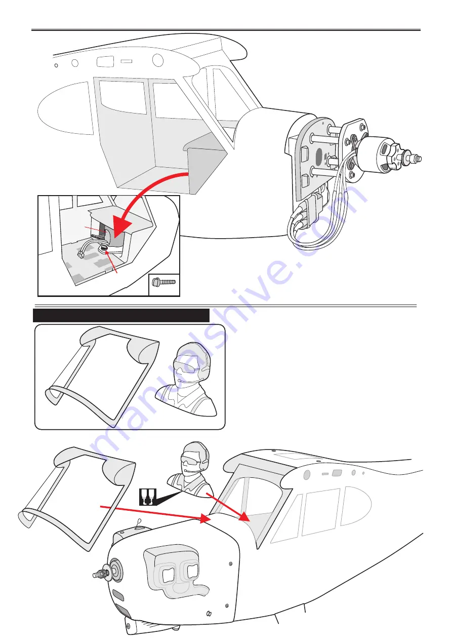
INSTALLING COCKPIT FUSELAGE
6x20mm
Screw
Battery
B
A
TOP SIDE
Page 1: ...main gear and spring wire for tail gear included Parts listing required not included Radio 04 channels Servo 05 06 servos Engine NGH GT 9 9cc gas motor Motor Brushless outrunner 1000 1800W 400 800KV P...
Page 2: ...ulding notes 3 Suggestion 3 Flight warnings 3 Covering tools 4 Adhesives and required tools 4 Academy of Model Aeronautics National Model Aircraft Safety Code 4 Parts listing not included 6 Tool suppl...
Page 3: ...ust as the dust will blow back into your eyes Always wear safety goggles a particle mask and rubber gloves when grinding drilling and sanding fiberglass parts Vacuum the parts and the work area thorou...
Page 4: ...ht including fuel of 55 pounds unless in compliance with the AMA Large Model Airplane program AMA Document 520 A f Ensure the aircraft is identified with the RYAN and address or AMA number of the owne...
Page 5: ...AMA Documents 922 and 923 6 With the exception of events flown under official AMA Competition Regulations excluding takeoff and landing no powered model may be flown outdoors closer than 25 feet to an...
Page 6: ...bols used throughout this instruction manual comprise Use a pencil to mark Wire cutters Hex Wrench Threadlocker screw cement Hand or electric drill cm 1 2 3 4 5 6 7 8 9 10 Straight edge ruler Some mor...
Page 7: ...ind Nut 4mm Flat Washer 4 4mm Spring Washer 4 4mm Flat Washer 4 4 4x60mm Socket Head Cap Screw 3x15mm Cap Screw 4 3mm Spring Washer 4 14 4mm Flat Washer 4 4 4mm Spring Washer 4 3x25mm Cap Screw 4 3mm...
Page 8: ...onto the aileron servos 2 Using a modeling knife remove the covering from over the pre cut servo arm exit hole on the aileron servo tray hatch This hole will allow the 1 2 C A C A INSTALLING THE AILER...
Page 9: ...Pull out servo cord with string 1 2 o 90 Aileron approx 16mm 2mm 2 Aileron servos 2 2x10mm Screw 2 For Aileron 1 5 mm 2 m m Screw 1 5 mm 1 5 mm 2 For Aileron Bottom view For Aileron servo 6 Repeat st...
Page 10: ...le of the wing 5 Center the aileron and hold it in place using a couple of pieces of masking tape 6 With the aileron and aileron servo centered carefully place a mark on the aileron pushrod wire where...
Page 11: ...Flaslink Push rod 4 2 Servo arm Instruction manual PIPER J 3 CUB Item code BH04 11 Bottom view Mark the spot to attach Bend 90o 1 2 Control Horn...
Page 12: ...der and throttle servos Test fit the servos into the servo tray Trim the tray if necessary to fit your servos 2 Mount the servo to the tray using the mounting screws provided with your radio system 90...
Page 13: ...lizer in its slot Make sure the horizontal stabilizer is square and centered to the fuselage by taking measurements but don t glue anything yet Check to mark sure the wing and stabilizer are paralell...
Page 14: ...the ailerons before see page 10 INSTALLING THE CONTROL HORNS AND LINKAGES 900mm Push rod 2 Nylon Clevis 2 Horn 2 1 Flaslink Duo rod connection lock 100mm Push rod 1 1 B A Horn 2 Elevator pushrod Horn...
Page 15: ...manual PIPER J 3 CUB Item code BH04 15 o Bend 90 Flaslink Servo arm 6mm Push rod Horn Elevator pushrod SetScrew Flaslink Elevator servo Elevator servo Flaslink Elevator pushrod Fuselage top side Cut...
Page 16: ...es for Rudder are glued the same way as the aileron before see page 8 Control horn and linkages for Rudder are installed the same way as the elevator before see page 13 14 INSTALLING THE CONTROL HORNS...
Page 17: ...servo Flaslink Flaslink 3mm Collar Set the tail wheel assembly in place on the plywood plate The pivot point of the tail wheel wire should be even with the rudder hinge line and the tail wheel bracke...
Page 18: ...oxy glue the nylon clasps as shown 3 Secure the tail wheel bracket in place using two 3mm x 15mm screw 4 Align the tail wheel wire so that the wire is parallel with the bottom of the rudder Secure 3x1...
Page 19: ...he long piece of wire used for the throttle pushrod One end of the wire has been pre bend in to a Z bend at the factory This Z bend should be inserted into the throttle arm of the engine when the engi...
Page 20: ...Instruction manual PIPER J 3 CUB Item code BH04 20 115mm Rubber Rubber Aluminium Aluminium 30mm Screw INSTALLING THE STOPPER...
Page 21: ...o the tank It may be necessary to remove some of the flashing around the tank opening using a modeling knife If flashing is present make sure none of it falls into the tank 5 When satisfied with the a...
Page 22: ...Instruction manual PIPER J 3 CUB Item code BH04 22 2 Clunks 1 1 1 Fuel Tank Fuel tank Fuel tank TOP SIDE TOP SIDE...
Page 23: ...throttle the throttle barrel should also open and close using this motion If not reverse the direction of the servo using the transmitter 3 Slide the adjustable metal connector servo arm assembly over...
Page 24: ...g Hold the cowl firmly in place using several pieces of masking tape MOUNTING THE COWL 4 While holding the cowl firmly in position drill four 1 6mm pilot holes through both the cowl and the side edges...
Page 25: ...Instruction manual PIPER J 3 CUB Item code BH04 25 3x12mm Tp Screw 4 3x12mm Tp Screw 2mm 3mm 2mm 3x12mm Tp Screw Fuselage Bottom side...
Page 26: ...heels 4mm Flat Washer 6 4mm Spring Washer 6 4x15mm Cap Screw 6 5x45mm Socket Head Cap Screw 2 2 5mm Flat washer 4 4 5mm Hex Nut 5mm Collar 5mm Hex Nut 5mm Collar 5x45mm Socket Head Cap Screw 5mm Flat...
Page 27: ...s through the fuselage side 3 Secure the switch in place using the two machine screws provided with the radio system 1 Plug the servo leads and the switch lead into the receiver You may want to plug a...
Page 28: ...Switch ON OFF Must be purchased separately X INSTALLING THE ELECTRIC MOTOR EP VERSION 6x20mm Cut 4 10x40mm Plastic M3 Blind Nut 4 4mm Flat Washer 4 4mm Spring Washer 4 4mm Flat Washer 4 4 4x60mm Sock...
Page 29: ...nual PIPER J 3 CUB Item code BH04 29 M3 Blind Nut 3x15mm Cap Screw 3mm Spring Washer Motor GP10 5030 400KV Battery 4x60mm Socket Head Cap Screw 10x40mm Plastic 4mm Spring Washer 4mm Flat Washer 4mm Fl...
Page 30: ...Instruction manual PIPER J 3 CUB Item code BH04 30 INSTALLING COCKPIT FUSELAGE 6x20mm 6x20mm Screw Battery B A TOP SIDE...
Page 31: ...Instruction manual PIPER J 3 CUB Item code BH04 31 Adhesive tape TOP SIDE Open Close Right Window...
Page 32: ...3x12mm Cap Screw 8 3mm Hex Nut 2 2 4 Ball link 4 Aluminium Fuselage Strut Attachment Aluminium Strut Attachment 2 Machined Strut Attachment 3mm Spring Washer Hair Pin Steel Strut Attachment Pin 4 2 14...
Page 33: ...tton Head Cap Screw 3x6mm Button Head Cap Screw 3x6mm Button Head Cap Screw 7mm 7mm 2 5mm 2 5mm 495mm 495mm B A Apply epoxy glue Drill holes using the stated in this case 2 5mm 2 5mm The number of tim...
Page 34: ...de BH04 34 The number of times the same way Assembly in this case twice 4 X 3x12mm Cap scew 3mm Spring Washer 3x12mm Cap scew Ball link 4 X Assemble left and right sides the same way L R L R BOTTOM SI...
Page 35: ...ocate the aluminium wing dihedral brace Test fit the aluminium tube dihedral brace into each wing haft The brace should slide in easily If not use 220 grit sand around the edges and ends of the brace...
Page 36: ...Instruction manual PIPER J 3 CUB Item code BH04 36 Secure Screw the wing panel in position Propeller Must be purchased separately X...
Page 37: ...ce it Doing this will help the airplane track straighter 1 Turn the airplane upside down Attach one loop of heavy string to the engine crankshaft and one to the tail wheel wire With the wings level ca...
Page 38: ...r more information refer to radio system instruction manual Follow instruction manual of Engine and Battery Engine Throttle Servo Receiver Battery Receiver Switch Aileron Elevator Elevator Servo Ailer...
Page 39: ...Instruction manual PIPER J 3 CUB Item code BH04 39 1 3 3 4 1 1 1 2a 2b 2b 2a 3 4 3 4 21 030 Cub Yellow ORACCOVER DECORATION Top view Bottom view Side view Left Side view Right...
Page 40: ...t Washer 4mm Spring Washer 4x25mm 4mm Spring Washer 3x25mm Cap Screw 4mm 3mm Hex Nut 4mm Flat Washer 3x12 mm Cap Scre w 3x12 mm Cap Scre w 3m m He x Nu t 3x15mm Tp Screw 3mm Spring Washe r 3x15mm Tp S...
Page 41: ...t up areas DO NOT dispose of empty fuel containers on a fire this can lead to an explosion NEVER fly in wet conditions or on windy or stormy days NEVER use damaged or deformed propellers or spinners T...
Page 42: ...del lands at the slowest possible speed Switch on the transmitter OFF ON OFF ON Check that the wings are correctly fitted to the fuselage If the model does not respond correctly to the controls land i...