Focke-Wulf FW190A-
Item code:BH87
INSTRUCTION MANUAL.
8
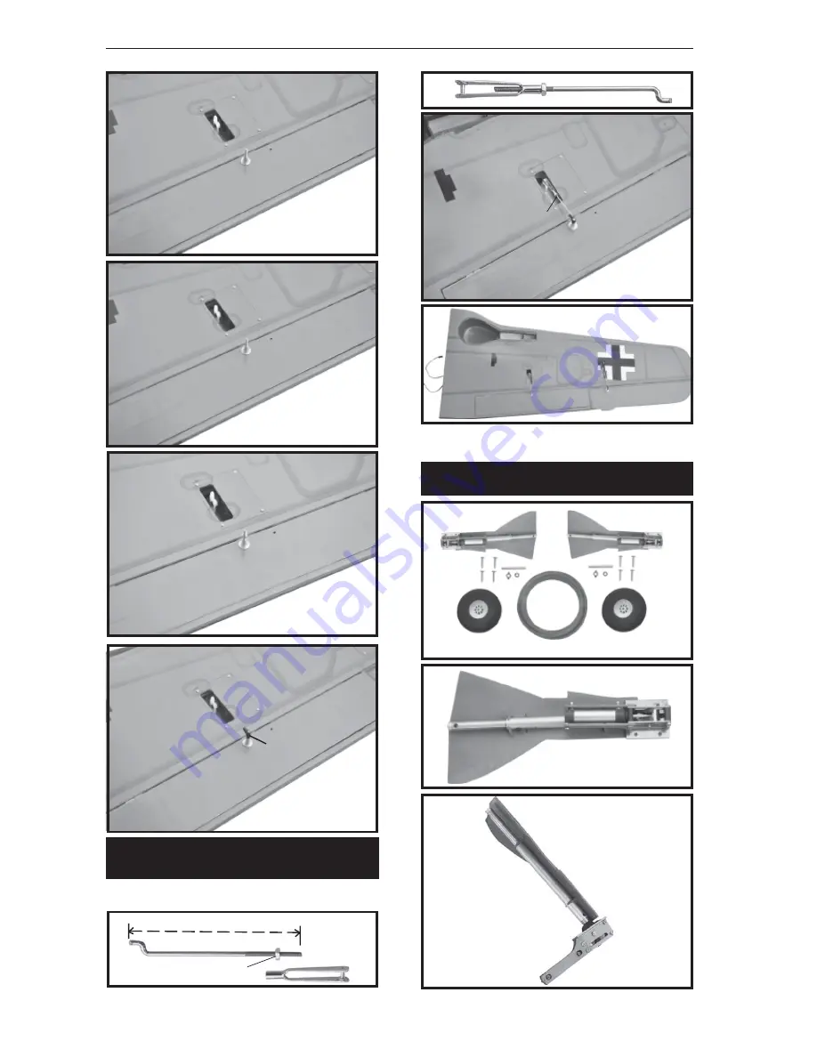
Installing the aileron linkages as pictures
below.
3.INSTALLING THE FLAP
LINKAGES.
Flap control
horn.
M2 lock nut
65mm
Repeat the procedure for the other wing
half
.
C/A glue
INSTALLING AIR RETRACTABLE
LANDING GEAR.
3 x 15mm
3 x 15mm


