12
VIDEO CCTV-A/V HUB
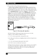
5. Run the hub’s power cord from the 5-pin DIN power inlet on its rear panel,
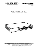
shown in Figure 3-3, to the nearest working AC power outlet. The Power LED
on its front panel, shown in Figure 3-4, should light up and stay on.
Figure 3-3. The hub’s rear panel.
Figure 3-4. The hub’s front panel.
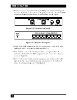
6. Connect the cable coming from the A/V source devices to the RJ-45 input
jack on the hub’s rear panel, as shown in Figure 3-5.
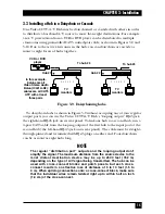
7. One at a time, connect the twisted-pair cables coming from the A/V
destination devices into the RJ-45 output jacks on the hub’s front-panel, as
shown in Figure 3-6.
8. Power on the source and destination equipment and send an audio/video
signal from the source. Verify the presence and quality of the audio and
video. If anything’s wrong, refer to
Section 4.1
.
Input
(RJ-45)
(RJ-45)
Normal outputs 1 through 8 (all RJ-45)
Looping output
Power
(5-pin DIN)
Power
LED

