10
VIDEO CCTV-A/V HUB
3. Place the Video CCTV-A/V Hub in its final location.
Before you run cabling from the hub to the baluns, you need to keep
maximum cabling distances in mind. Given the type of video (if any) you’re
transmitting and the type of UTP cable you’re using, the hub’s final location
must be within maximum distance specs of the source and destination devices
(see the
Maximum Distance
specification in
Chapter 1
). These distances
assume that the cable used conforms to the
Cable Required
specification in
Chapter 1
. Note that every cable and device interconnection is equivalent to
10 ft. (3 m) of cable and must be included in the maximum cable length
calculation. If you’re not sure of your cable length, you can estimate it by
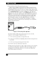
performing a DC resistance test with a digital ohmmeter, as shown in
Figure 3-1. 1000 feet (305 m) of 24-AWG cable should give a reading of
approximately 26 ohms (52 ohms if you are measuring at one end with the
opposite cable ends shorted).
Figure 3-1. Measuring cable impedance.
The Video CCTV-A/V Hub must be kept away from sources of radio-
frequency or electromagnetic radiation; at least:
a) 5" (12.7 cm) from power lines carrying 2 kVA or less.
b) 12" (30.5 cm) from fluorescent lighting and power lines carrying between
2 and 5 kVA.
c) 36" (91.4 cm) from power lines greater than 5 kVA.
d) 40" (101.6 cm) from transformers and motors.
You’ll get the best performance by using a single continuous run of cable. Do
not use flat-satin cable (that is, cable whose wires aren’t twisted), even for
patching short runs. Flat-satin cable acts as an antenna and will pick up
nearby radio-frequency interference.
METER
Hub end
UTP
Balun end

