background image















14







 













®

SECT 4

Special configuration

Configuration

You can alter the way that the Wizard extender modules operate to suit your 
requirements. This is done using the Configuration mode and you can affect the 
following settings: 

•  

Password setting

 – allows you to lock the remote module to prevent 

unauthorised system access.

•  

Mouse restoration and settings

 – allows you to restore mouse operation and 

also to change the mouse type.

•  

Image controls - sharpness & brightness

 – allows you to manually adjust the 

video image to ensure that it is crisp and bright.

•  

Skew adjustment

 – allows you to manually compensate for possible video 

errors introduced by long, uneven cable connections.

•  

Miscellaneous functions

 – report firmware version and restore settings.

What are hotkeys?

Hotkeys are two normal keyboard keys that, when pressed simultaneously with a 
third key, signal to the Wizard extender modules that you are sending a message 
specifically to them and not to the computer. The hotkeys are ordinarily 

 and 

, while a third keypress determines what you want the modules to do.

If the standard 

 and 

 hotkeys are also needed for computer tasks, you 

can change them for another combination using switches 2 and 3 on the 
REMOTE module:

2 OFF
3 OFF  

Hotkeys = 

 and 

 (default setting)

2 OFF
3 ON  

Hotkeys = 

 and 


2 ON
3 OFF  

Hotkeys = 

 and 

2 ON
3 ON  

Hotkeys disabled 

Entering, using and exiting configuration mode

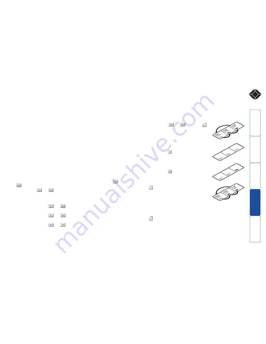
To enter and use configuration mode:

1  Simultaneously press the currently configured 

hotkeys (by default, 

 and 

) along with 


The three keyboard indicators (‘Num Lock’, ‘Caps 
Lock’ and ‘Scroll Lock’) will now begin to flash in 
sequence to show that you are in configuration 
mode. 

2  Press the first letter of the required configuration 

option, for instance  . 

All three keyboard indicators will illuminate 
continuously.

3  Press the number of the required configuration 

option, for instance  .  

The ‘Scroll Lock’ indicator will extinguish, leaving 
the ‘Num Lock’ and ‘Caps Lock’ indicators lit.

4  Press 

 to confirm your option.

The three keyboard indicators (‘Num Lock’, ‘Caps 
Lock’ and ‘Scroll Lock’) will now begin to flash in 
sequence again.

To exit from configuration mode:

1  Within configuration mode, the three keyboard indicators should be flashing 

in sequence to show that the module is ready to receive a new command.

2  Press 

The three indicators will return to their normal states.


Num

Loc

k

Cap

s

Loc

k

Scroll

Loc

k

Nu

m

Loc

k

Cap

s

Loc

k

Scroll

Loc

k

Summary of Contents for ServSwitch ACU5114A

Page 1: ...U S call 724 746 5500 FREE technical support 24 hours a day 7 days a week Call 724 746 5500 or fax 724 746 0746 Mailing address Black Box Corporation 1000 Park Drive Lawrence PA 15055 1018 Web site www blackbox com E mail info blackbox com CUSTOMER SUPPORT INFORMATION November 2006 ACU5114A ACU5116A ...

Page 2: ... configuration mode 14 Password setting 15 Password override 15 Hot plugging and mouse restoration 16 Which restore setting do I use 16 Microsoft and Logitech specific mouse settings 16 Image controls sharpness and brightness 17 Skew adjustment 18 Miscellaneous settings 19 Flash upgrade 20 Stage A Download the upgrade files 20 Stage B Create a startup diskette 20 Copy the downloaded files to the d...

Page 3: ...tenders allow you to place a duplicate keyboard video monitor mouse audio accessories and a serial device up to 300 metres from a computer system Two users can simultaneously view the output of the host system and either can take control providing it is not being used by the other user A user relinquishes control two seconds after their last key press or mouse movement ACU5114A and ACU5116A varian...

Page 4: ...lti cable for keyboard video and mouse connections between computer and LOCAL module Serial cable for RS232 connection between computer and LOCAL module CPU KVM SW ITCH VIDEO OUT T O R E M O T E P O W E R Wizard Extender LOCAL 724 746 5500 LOCAL extender module Connection from computer RS232 serial port Optional power supply connection Switch bank to determine certain modes and functions Connectio...

Page 5: ...ouse and audio connections between computer and LOCAL module Serial cable for RS232 connection between computer and LOCAL module CPU KVM SW ITCH VIDEO OUT T O R E M O T E P O W E R Wizard Extender LOCAL 724 746 5500 LOCAL ACU5116A module Connection from computer RS232 serial port Optional power supply connection Switch bank to determine certain modes and functions Connection to REMOTE module Multi...

Page 6: ...MIC input on the REMOTE unit LOCAL Switch 4 OFF Normal operation ON Suspend operation and reset the LOCAL module Use this setting momentarily to produce the same effect as removing and restoring power if incorrect operation has occurred Return the switch to the OFF position to allow normal operation to continue Installation The installation of the Wizard extenders is straightforward and can best b...

Page 7: ...e REMOTE module that the next key to be pressed is a special configuration command for the module and is not to be passed to the computer system 2 OFF 3 OFF Hotkeys CTRL and SHIFT 2 OFF 3 ON Hotkeys ALT and SHIFT 2 ON 3 OFF Hotkeys CTRL and ALT 2 ON 3 ON Hotkeys disabled REMOTE Switch 4 This switch is reserved for future use Note When shipped all switches are set in the OFF positions and this will...

Page 8: ...t is inserted into the rack therefore check all settings before insertion 1 Place the supplied rack plate s onto the front of the module and secure it with the countersunk screws 2 Orient the module on its side so that its labelled face is the correct way up and the securing plate s is are facing away from the rack 3 Slide the module into the required rack position The rectangular cut out in the f...

Page 9: ...Speaker or SPK Light green Microphone or MIC Pink or maroon Serial cable connection The Wizard extender modules offer the option to attach an RS232 serial device such as a touch screen input via the remote link The link supports software or hardware handshaking up to a maximum baud rate of 56Kb s To make the serial connection between the LOCAL module and your computer system use the supplied seria...

Page 10: ... blue D type socket labelled VIDEO OUT on the LOCAL module 2 Connect the keyboard lead to the purple mini DIN socket labelled on the LOCAL module 3 Insert the keyboard lead into the green mini DIN socket labelled on the LOCAL module CPU KVM SW ITCH VIDEO OUT Connection from video monitor Connection from keyboard Connection from mouse LOCAL LOCAL Optional power connector not required unless the hos...

Page 11: ... connector from the twisted pair cable link into the socket marked TO LOCAL 2 Attach the output connector of the power supply to the socket at the front edge of the REMOTE module labelled POWER 3 If a serial connection is to be used attach the lead from your serial device to the 9 way male connector on the REMOTE module labelled Power supply connection 1 Insert the IEC connector of the supplied po...

Page 12: ...rophone LOCAL switch 3 ON stereo line in 1 Connect the microphone or stereo line input plug to the REMOTE module socket labelled Note Ensure that the setting of switch 3 on the LOCAL module matches the input to this socket OFF microphone ON stereo line input 2 Connect the speaker plug to the socket labelled Note When the REMOTE module is rack mounted the audio connections must be made after the mo...

Page 13: ...deo monitors continuously receive the output from the host system Control of the host system is arbitrated by the Wizard extender modules on a first come first served basis In the idle state control is available to both users and their keyboard indicators both show the current Num Lock etc conditions of the host system At the moment that a key is pressed or a mouse is moved the keyboard and mouse ...

Page 14: ...and the three keyboard indicators will begin alternately flashing between the Num Lock and Scroll Lock and Caps Lock This sequence indicates that a password is required To unlock the system 1 Enter the correct password and press Note Passwords are NOT case sensitive Note If an invalid password has been entered and the keyboard indicators are not flashing as described above press to clear the incor...

Page 15: ...eeded for computer tasks you can change them for another combination using switches 2 and 3 on the REMOTE module 2 OFF 3 OFF Hotkeys and default setting 2 OFF 3 ON Hotkeys and 2 ON 3 OFF Hotkeys and 2 ON 3 ON Hotkeys disabled Entering using and exiting configuration mode To enter and use configuration mode 1 Simultaneously press the currently configured hotkeys by default and along with The three ...

Page 16: ...d unlocking the system section in the Installation and operation chapter Password override This mode allows you to override the password that has been set at the REMOTE module and place it into configuration mode so that a new one may be set This feature is particularly useful when passwords have been lost or forgotten To override the REMOTE password 1 Remove power from the REMOTE module 2 With po...

Page 17: ...ally state that it is an Intellimouse on its underside label Recognising an Intellimouse driver Before hot plugging your Wizard extender modules or afterwards using only keyboard control access the Windows Control Panel and select either the Mouse option on Windows NT 2000 and XP or the System option on Windows 95 98 ME Look for the name of the driver which will usually include the words PS 2 or I...

Page 18: ...o flash in sequence The speed of the sequence indicates the level of the sharpness adjustment currently applied the slower the rate the lower the level of sharpness being applied 2 While viewing the displayed high contrast screen image use the following keys to adjust the controls High contrast black character on white background Black or bright white shadow on the right indicates the need for sha...

Page 19: ...tern it is much easier to discover which if any colours are being adversely affected by the twisted pair cable run 4 As appropriate press either the R G or B keyboard keys to select the appropriate colour channel Corresponding keyboard indicators will flash rapidly to show which channel is currently selected for adjustment Num Lock for Red Caps Lock for Green and Scroll Lock for Blue Convergence t...

Page 20: ...ning an application that can display typed keys as screen characters e g a word processor or Windows Notepad The current firmware version will be written to the application in the form of the letter V followed by three numbers for example V201 means version 2 01 Reset all configuration options to default states Returns all user configurable options to the settings that are installed at manufacture...

Page 21: ...sed by the SSWExxx EXE to select the appropriate one SSWExxxD HEX this is the firmware file for the LOCAL module SSWExxxR HEX this is the firmware file for the REMOTE module Where xxx is the upgrade version number Now please follow Stage B Stage B Create a startup diskette For this stage you will need a 31 2 floppy diskette that is either blank or has existing contents that are no longer required ...

Page 22: ...t of the computer Connect the other end of the cable to the keyboard port of the REMOTE module This is the only connection required 3 On the REMOTE module change switch 1 to the ON position 4 Attach the power supply unit to the POWER input of the REMOTE module and connect the mains lead to a nearby wall socket 5 Switch on the computer The upgrade process will start automatically and confirmation w...

Page 23: ...ontrol is set too high the monitor may not be able to display a picture Try reinstating the factory default sharpness settings Please refer to the Image controls sharpness and brightness section in the Special Configuration chapter Temporarily disconnect the video link to the LOCAL module connect a monitor directly to the computer video port and check for a correct video image output The keyboard ...

Page 24: ...tal ampere rating of all the devices plugged into the wall outlet does not exceed the wall outlet s ampere rating Do not attempt to service the Wizard modules yourself The Wizard modules and power supplies can get warm in operation do not situate them in an enclosed space without any ventilation The Wizard modules do not provide ground isolation and should not be used for any applications that req...

Page 25: ...etween the equipment and the receiver c Connect the equipment to an outlet on a circuit different from that to which the receiver is connected d Consult the supplier or an experienced radio TV technician for help FCC Compliance Statement United States This equipment generates uses and can radiate radio frequency energy and if not installed and used properly that is in strict accordance with the ma...

Page 26: ...Repairs to certified equipment should be made by an authorized Canadian maintenance facility in this case your supplier Any repairs or alterations made by the user to this equipment or equipment malfunctions may give the telecommunications company cause to request the user to disconnect the equipment Users should ensure for their own protection that the electrical ground connections of the power u...

Page 27: ...por los orificios de ventilación 10 El equipo eléctrico deber ser situado fuera del alcance de fuentes de calor como radiadores registros de calor estufas u otros aparatos incluyendo amplificadores que producen calor 11 El aparato eléctrico deberá ser connectado a una fuente de poder sólo del tipo descrito en el instructivo de operación o como se indique en el aparato 12 Precaución debe ser tomada...

Page 28: ...01 888 800 358 201 888 808 tuki blackbox fi France www blackbox fr 33 1 45 606 717 33 1 45 606 747 tech blackbox fr Germany www black box de 49 811 5541 110 49 811 5541 499 techsupp black box de Ireland www blackbox co uk 353 1 662 2466 353 1 662 2477 techhelp blackbox co uk Italy www blackbox it 39 02 27 404 700 39 02 27 400 219 supporto tecnico blackbox it Netherlands www blackbox nl 31 30 241 7...

Page 29: ... ctxd com Documentation by 2006 Black Box Corporation All trademarks are acknowledged Black Box Corporation 1000 Park Drive Lawrence PA 15055 1018 United States of America Tel 1 724 746 5500 Fax 1 724 746 0746 ...

Page 30: ... NETWORK SERVICES Copyright 2006 Black Box Corporation All rights reserved 1000 Park Drive Lawrence PA 15055 1018 724 746 5500 Fax 724 746 0746 ...

Reviews: