background image

CITYLIGHT FIBRE CHANNEL CARD

15

Rail Voltage

The voltage actually present at the card. In non-redundant PSU chassis this
can be used to monitor the state of the power supply and should always be
greater than 4.9V.

PSU

This field gives an indication of the operating state of the PSUs in the
CityLIGHT chassis associated with the transceiver displayed, i.e. the local or
remote CityLIGHT chassis.  The displayed state of the PSUs can be any one
of the following:

i) 

Good.

ii)  Under voltage (the voltage on the card is too low).

iii)  Over voltage (the voltage on the card is too high).

Serial Number

This field gives the serial number of the CityLIGHT Fibre Channel Card in the
selected slot of the CityLIGHT management chassis.

Firmware Version Number

The factory loaded firmware version resident on the Fibre Channel Card.

Location

The location is entered by the user; see CityLIGHT SNMP Card installation
manual for details.

Other Managed Features

The CityLIGHT SNMP Card also monitors the PSUs and cooling fans of
chassis.  Refer to the installation manual supplied with the CityLIGHT SNMP
Card for more details.

2.8 Shipping Contents

The shipping carton contains:

This manual (1)

CityLIGHT Fibre Channel Card (1)

Summary of Contents for LCL931A

Page 1: ...S 24 hours 7 A M Monday to midnight Friday 877 877 BBOX FREE technical support 24 hours a day 7 days a week Call 724 746 5500 or fax 724 746 0746 Mail order Black Box Corporation 1000 Park Drive Lawrence PA 15055 1018 Web site http www blackbox com E mail info blackbox com CUSTOMER SUPPORT INFORMATION ...

Page 2: ...in a commercial environment Operation of this equipment in a residential area is likely to cause interference in which case the user at his own expense will be required to take whatever measures may be necessary to correct the interference Changes or modifications not expressly approved by the party responsible for compliance could void the user s authority to operate the equipment This digital ap...

Page 3: ...icamente con carritos o pedestales que sean recomendados por el fabricante 7 El aparato eléctrico debe ser montado a la pared o al techo sólo como sea recomendado por el fabricante 8 Servicio El usuario no debe intentar dar servicio al equipo eléctrico más allá a lo descrito en las instrucciones de operación Todo otro servicio deberá ser referido a personal de servicio calificado 9 El aparato eléc...

Page 4: ...iado únicamente de acuerdo a las recomendaciones del fabricante 15 En caso de existir una antena externa deberá ser localizada lejos de las lineas de energia 16 El cable de corriente deberá ser desconectado del cuando el equipo no sea usado por un largo periodo de tiempo 17 Cuidado debe ser tomado de tal manera que objectos liquidos no sean derramados sobre la cubierta u orificios de ventilación 1...

Page 5: ...e situations Repairs to certified equipment should be made by an authorized Canadian maintenance facility in this case your supplier Any repairs or alterations made by the user to this equipment or equipment malfunctions may give the telecommunications company cause to request the user to disconnect the equipment Users should ensure for their own protection that the electrical ground connections o...

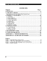
Page 6: ...gonomics 13 2 6 Power Supply 13 2 7 Management 13 2 8 Shipping Contents 15 3 INSTALLATION 16 3 1 Tools Required 16 3 2 Before You Start 16 3 3 General Set Up 16 4 DIAGNOSTIC LEDS 19 5 SWITCH POSITIONS 20 APPENDIX A TROUBLESHOOTING 22 APPENDIX B GLOSSARY OF TERMS 24 Figures Figure 1 CityLIGHT Fibre Channel Card 10 Figure 2 Three Sites Backhauled to a Central Office 12 Figure 3 Linking Two Sites Man...

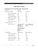
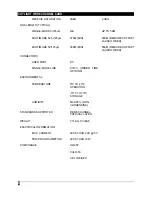
Page 7: ...Bm 0dBm RECEIVE SENSITIVITY 20dBm 20dBm RECEIVE SATURATION 6dBm 6dBm LINK LENGTH TYPICAL SINGLE MODE 9 125µm UP TO 15KM SHORT HAUL BASED ON WORK CASE 6PS NM KM FIBER LONGER DISTANCES CAN BE ACHIEVED ON HIGHER SPECIFICATION FIBER UP TO 40KM LONG HAUL POWER BUDGET LIMITED USER FIBER LINK MULTIMODE 850 SINGLE MODE 1300 TYPICAL POWER BUDGET 12dB 12dB MIN POWER BUDGET 7 5dB 7 5dB TYPICAL LAUNCH POWER 5...

Page 8: ...0M MIN 550M REQUIRES OFFSET LAUNCH FIBER CONNECTORS USER PORT SC SINGLE MODE LINK SC FC ORDER TIME OPTIONS ENVIRONMENTAL TEMPERATURE 0 C TO 40 C OPERATION 10 C TO 70 C STORAGE HUMIDITY MAX 95 NON CONDENSING STANDARDS SUPPORTED FIBRE CHANNEL PHYSICAL LAYER WEIGHT 0 15KG 0 33LBS ELECTRICAL INFORMATION MAX CURRENT LESS THAN 2 0A 5V POWER CONSUMPTION LESS THAN 10W COMPLIANCE UL1950 CUL1950 CE 73 23 EE...

Page 9: ... CARD 9 CE 89 336 EEC FCC PT 15 LIMIT B CARD VARIANTS LCL931A LCL932A LCL933A LCL934A FIBRE CHANNEL MM SC TO SM SC 15 KM FIBRE CHANNEL SM SC TO SM SC 15 KM FIBRE CHANNEL MM SC TO SM SC 40 KM FIBRE CHANNEL SM SC TO SM SC 40 KM ...

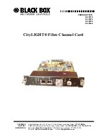
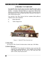
Page 10: ...iber using short haul optics or 40km using long haul optics Two versions of the Fibre Channel Card are available offering different interfaces to the user s equipment a 850nm Multimode b 1300nm Single mode Figure 1 CityLIGHT Fibre Channel Card 2 1 Data Rate The CityLIGHT Fibre Channel Card transmits at a data rate of 1062 Mbps 2 2 Drive Distance The CityLIGHT Fibre Channel Card allows a user to co...

Page 11: ...rnal attenuation will be necessary to prevent optical overload and the inevitable data errors For these applications an external 10dB attenuator is available to ensure that the optical receive power falls within the operating limits of the receiver The fixed value 10dB attenuator LCL505A is of a doped fiber design which eliminates the troublesome reflections which an air gap attenuator may introdu...

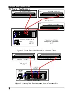
Page 12: ... Site 3 CENTRAL OFFICE Fiber System Link CityLIGHT 16 Slot Chassis CityLIGHT 1U Chassis CityLIGHT 1U Chassis CityLIGHT 1U Chassis Figure 2 Three Sites Backhauled to a Central Office Pwr 1 Pwr 2 Management RemF RX Al Rx Tx Cu Lk 10 100 Ethernet Pwr Rx Al Link Link Rx Al ATM 155 Rem F Token Cu Ins RX Al Data Bcn 4 16 Token Ring Rem F RemF RX Al Rx Tx Cu Lk 10 100 Ethernet RemF RX Al Rx Tx Cu Lk 10 1...

Page 13: ... Once installed in a chassis with an SNMP card or connected via the fiber to a card in an SNMP managed chassis the SNMP agent automatically detects the card and displays the following information NOTE This information is the same for the local and remote cards and is available via the terminal interface as well as the SNMP MIB i Card Type ii Fiber Port Link Status iii Temperature iv Fan Status v L...

Page 14: ...ltimode port iii ACTIVE both ends are inserted and carrying data Temperature This is the temperature of the CityLIGHT Fibre Channel Card A trap alarm is generated if the temperature is not within the required range NOTE This temperature monitors the actual temperature of the electronics on the card Acceptable values are from 10 C to 70 C Fan Status The 1U Chassis has fan assisted cooling The SNMP ...

Page 15: ...n the card is too low iii Over voltage the voltage on the card is too high Serial Number This field gives the serial number of the CityLIGHT Fibre Channel Card in the selected slot of the CityLIGHT management chassis Firmware Version Number The factory loaded firmware version resident on the Fibre Channel Card Location The location is entered by the user see CityLIGHT SNMP Card installation manual...

Page 16: ...uration Check that the connections on the CityLIGHT Fibre Channel Card the patch cords used and the site requirements are compatible As the CityLIGHT Fibre Channel Card is a long distance product installation is greatly simplified with a technician at each end of the link This allows link tests to be completed in the least amount of time 3 3 General Set Up 1 If an SNMP Card is used on the link set...

Page 17: ...ed light level is between 6dBm and 20dBm If the received light level is greater than 6dBm an attenuator is required 10 Connect the fiber cable to the receiver Rx connector Make sure the Single mode Alarm LED is extinguished see Section 4 Diagnostic LEDs If the Alarm LED is illuminated check that the receive power is greater than 20dBm If it is less than 20dBm check the launch power of the far end ...

Page 18: ...for possible causes NOTE During commissioning most faults are associated with bad wrong cabling dirty connectors incorrect patching loss of power or excessive power budget The hardware installation is now complete To enable management refer to the Management Serial Interface section of the CityLIGHT Card installation manual ...

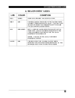
Page 19: ... PATH FROM THE TRANSMITTER OF THIS CARD TO THE FAR END CARD RECEIVER LINK RED GREEN RED A RECEIVE ALARM CONDITION EXISTS ON THE USER PORT CHECK THE FIBER CONNECTED TO THE LOCAL EQUIPMENT AND CHECK THAT THE LOCAL EQUIPMENT IS POWERED UP GREEN THE LINK TO THE LOCAL CUSTOMER EQUIPMENT IS GOOD ALARM RED THIS INDICATES THAT A SIGNAL HAS NOT BEEN DETECTED ON THE SINGLE MODE FIBER PORT I E THE RECEIVED L...

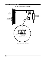
Page 20: ...TYLIGHT FIBRE CHANNEL CARD 20 5 SWITCH POSITIONS R L 5 4 3 2 1 L Local R Remote Must be set as shown Factory Test ON ON Backplane Connector Optical Link Interface User Interface Figure 4 Switch Positions ...

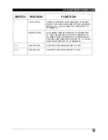
Page 21: ...ST BE SET TO L LOCAL AND THE OTHER SET TO R REMOTE 1 REMOTE ON IF AN SNMP CARD IS PRESENT AT EITHER END OF THE LINK SET BOTH CARDS TO REMOTE IF NO SNMP CARD IS PRESENT AT EITHER END OF THE LINK ONE CARD MUST BE SET TO L LOCAL AND THE OTHER SET TO R REMOTE 2 3 ALWAYS OFF FACTORY TEST MUST BE SET TO OFF 4 5 ALWAYS ON FACTORY TEST MUST BE SET TO ON ...

Page 22: ... POWER OF THE USER EQUIPMENT AND CHECK IT IS WITHIN THE RANGE SPECIFIED FOR THE INTERFACE TYPE SEE APPENDIX B TECHNICAL DATA THE REM F LED IS RED THERE IS A FAULT IN THE FIBER PATH FROM THE SINGLE MODE TX PORT ON THE CITYLIGHT FIBRE CHANNEL CARD TO THE REMOTE CARD CHECK THE TRANSMIT LINK FROM THIS FIBRE CHANNEL CARD TO THE REMOTE CARD RECEIVER CHECK THAT THE REMOTE RECEIVE LIGHT LEVEL IS GREATER T...

Page 23: ...T FIBRE CHANNEL CARD IS 2DBM FOR THE SHORT HAUL UNIT AND 0DBM FOR THE HIGH POWER UNIT If after going through the troubleshooting section you fail to resolve your problem and require more help please contact Black Box Technical Support at 724 746 5500 with the following information 1 Unit type 2 Unit serial number 3 Environment lay out Include hubs bridges and routers with model numbers estimated c...

Page 24: ...ITTEN IN ABSTRACT SYNTAX NOTATION 1 ASN1 THAT IS USED WITH SNMP MANAGEMENT SYSTEMS MULTIMODE AN OPTICAL FIBER IN WHICH LIGHT PROPAGATES DOWN THE FIBER IN MULTIPLE MODES PSU POWER SUPPLY UNIT RX RECEIVE SINGLE MODE AN OPTICAL FIBER IN WHICH LIGHT TRAVELS IN ONE MODE WHICH DOES NOT INTRODUCE MODAL DISPERSION CONSEQUENTLY SINGLE MODE FIBER MAY HAVE GREATER DISTANCE CAPABILITY THAN MULTIMODE SNMP SIMP...

Page 25: ... Copyright 1999 Black Box Corporation All rights reserved 1000 Park Drive Lawrence PA 15055 1018 724 746 5500 Fax 724 746 0746 ...

Reviews: