15
CHAPTER 3: Installation
NOTE
We recommend working with the tubes in sequential order to maintain
installation organization.
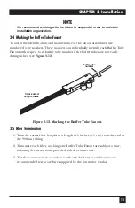
3.4 Marking the Buffer Tube Fanout
To aid in the identification and maintenance of the fanout assemblies, use
numbered wire markers. These markers can individually identify each Buffer Tube
Fanout with respect to its buffer tube number if the buffer tubes are not easily
distinguished (see
Figure 3-12
).
Figure 3-12. Marking the Buffer Tube Fanout.
3.5 Fiber Termination
1. Trim the excess fiber lengths to a length of 2 inches (5.1 cm) from the end of
the 900-µm tubing.
2. Terminate each fiber, working one Buffer Tube Fanout assembly at a time,
following the instructions provided with the connectors.
3. Test the connectors in accordance with standard test procedures or any
recommended test procedures supplied by the connector vendor.
Color-coded
900-µm tubes
Buffer tube
number
Summary of Contents for EFN06-24
Page 3: ......


