11
CHAPTER 3: Installation
IMPORTANT
Make sure that the fibers are clean and dry. Any residue left on the fiber
will obstruct threading operations into the 900-µm assembly pieces.
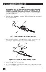
6. Place the crimp tabs of the bottom piece of the Buffer Tube Fanout on the
end of the buffer tube. Press the tab with pliers to secure the Buffer Tube
Fanout bottom to the end of the tube (see
Figure 3-6
).
CAUTION
Be careful not to crush the tube. Crimp only until the tube begins to
deform. Spaces between the ends of the crimp tabs are normal for most
applications.
Check the crimp for effectiveness by pulling on and twisting the tube. The
tube should not move when pulling gently on it.
Figure 3-6. Securing the Buffer Tube Fanout Bottom to the End of the
Tube.
3.3 Threading the Fibers
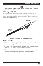
1. Approximately 2 inches (5 cm) off to either side of the tube and Buffer Tube
Fanout bottom, use strapping tape to secure the plastic section of the 900-µm
assembly to the table’s edge as shown in
Figure 3-7
.
NOTE
The plastic section 900-µm assembly has color-coded legs and
corresponding numbers on its plastic housing. The number 1, or blue
tube should be on the front bottom right corner of the assembly.
2. Separate and untangle the number 1 (blue) fiber back to the point where it
exits the buffer tube.
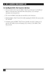
Tabs
Summary of Contents for EFN06-24
Page 3: ......


