background image

DCX Switch

877-877-2269   |   blackbox.com 

Page 54

  Name 

Overall Screening 

Pair Shielding

 U/UTP 

û


û

 F/UTP 

ü


û

 U/FTP 

û


ü

 S/FTP 

ü


ü 


or S/STP 

 or PiMF

U/UTP

F/UTP

U/FTP

S/FTP 

S/STP 

PiMF

Pair shielding

Overall screening

Outer sheath

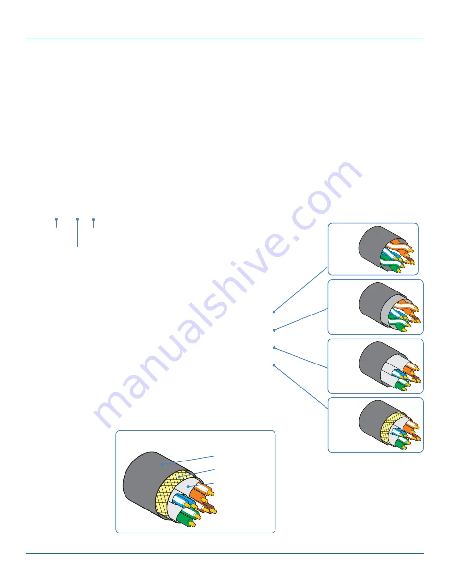
General cable anatomy

Overall 

screening

Pair 

shielding

Twisted 

Pair

Appendix C. Link cable interference protection

While the Category rating (e.g. CAT 5e, CAT 6a, CAT 7, etc.) determines the electrical performance of a cable, another vital part 
of the overall cable specification is its protection from interference. As cabling distances and data rates increase, so too does the 
susceptibility to interference, from both external and internal sources. 

Proximity to other electromagnetic sources are the main external threat and these can be subdued using overall screening that 
surrounds all four of the cable pairs. However, interference is also possible from neighbouring twisted pairs within the same cable 
and this can be just as hazardous to data integrity. Such 

crosstalk 

is countered by shielding each cable pair separately. 

Within each Category rating, you can specify different combinations of external screening and internal shielding to suit the envi-
ronment into which the link is being placed. 

Interference protection codes

Interference protection is classified in the following manner:

U/UTP

where

U = unshielded
F = foil shielding
S = braided shielding
PiMF = Pairs in Metal Foil

Summary of Contents for DCX-VGA

Page 1: ...es are required DCX KVM Matrix Switch DCX1000 DCX3000 DPT DCX VGA DCX3000 DCX3000 DVR DCX3000 DVT Order toll free in the U S or for FREE technical support 24 7 Call 877 877 BBOX outside U S call 724 7...

Page 2: ...Any other trademarks mentioned in this manual are acknowledged to be the property of the trademark owners We re here to help If you have any questions about your application or our products contact Bl...

Page 3: ...wn expense will be required to take whatever measures may be necessary to correct the interference Changes or modifications not expressly approved by the party responsible for compliance could void th...

Page 4: ...el flujo de aire por los orificios de ventilaci n 10 El equipo el ctrico deber ser situado fuera del alcance de fuentes de calor como radiadores registros de calor estufas u otros aparatos incluyendo...

Page 5: ...ower 15 3 1 13 Console connections Video 16 3 1 14 Console connections USB 17 3 1 15 Console connections Audio 17 3 1 16 Console connections Data link 18 3 1 17 Console connections Options port 18 3 1...

Page 6: ...tions The following options are available for your DCX installation DCX1000 digital matrix switch with 10 ports DCX3000 digital matrix switch with 30 ports DCX SAM module with DisplayPort video and US...

Page 7: ...computers and consoles can be individually connected in order to take advantage of the DCX extender properties without the switching COMPUTER COMPUTER COMPUTER COMPUTER DCX Switch DCX DVR Remote DCX...

Page 8: ...LY or SHARED ACCESS for the same computer EXCLUSIVE The console user can view and control the chosen computer s output Once selected other consoles can simultaneously use VIEW ONLY for the same comput...

Page 9: ...R DCX3000 Switch K V M M A T R I X S W I T C H I N G 1 11 2 12 3 13 4 14 5 15 6 16 7 17 8 18 9 19 10 20 COMPUTERS COMP OR USER COMP OR USER COMP OR USER COMP OR USER COMP OR USER COMP OR USER COMP OR...

Page 10: ...ter connections a DCX SAM module two versions available links to each computer Switch connections when used a DCX1000 or DCX3000 Switch unit sits at the heart of the system Console connections the per...

Page 11: ...3 1 3 Computer connections Data link Each DCX SAM module is linked via a shielded S FTP or S STP CAT6a or CAT7 cable either to a central DCX Switch module multi system matrix installation or directly...

Page 12: ...d S FTP or S STP CAT6a or CAT7 cable from the remote DCX DVR module to a vacant RJ 45 socket sockets 9 and 10 by default on the rear panel of the DCX1000 Switch These are NOT Ethernet network ports an...

Page 13: ...nverted to user ports see above 3 1 9 1 To connect a console link 1 Connect the shielded S FTP or S STP CAT6a or CAT7 cable from the remote DCX DVR module to a vacant RJ 45 socket on the front panel o...

Page 14: ...to the DCX1000 3000 unit or anywhere The auto sensing network port can determine between 10 100Mbps or 1Gbps links and can also adjust to straight or cross over cables 3 1 10 1 To connect a network li...

Page 15: ...pply socket 4 Where power redundancy is required repeat steps 1 to 3 for a second power adapter From the power adapter 3 1 12 2 To disconnect the power adapter 1 Isolate the power adapter from the mai...

Page 16: ...video cable from your video display to the video output port on the rear panel of the user module From your video display 3 1 13 2 EDID management The DCX1000 3000 Switches provide a number of fixed...

Page 17: ...ule From USB devices From USB devices Rear panel Front panel 3 1 15 Console connections Audio The DCX DVR module supports stereo speakers headphones and also a microphone port All audio devices are pr...

Page 18: ...exceed 50 meters 164 feet 3 1 16 1 To link the DCX DVR module 1 Connect a suitable shielded S FTP or S STP CAT6a or CAT7 cable to the LINK socket on the rear panel of the DCX DVR module Connect the ot...

Page 19: ...18 2 To disconnect the power adapter 1 Isolate the power adapter from the mains supply 2 Grasp the outer body of the power adapter plug where it connects with the module 3 Gently pull the body of the...

Page 20: ...the IP address of the DCX1000 3000 Switch The switch will attempt to contact a valid DHCP server to determine a suitable IP address If a DHCP server cannot be located then the switch will automatical...

Page 21: ...ork port 1 If you need to make a temporary connection for configuration purposes use a standard patch cable cross over or straight connections are both supported to link the Ethernet 10 100 network po...

Page 22: ...vailable page choices Information and options are displayed within the main section of the page Some items will provide further popup information when you hover your mouse pointer over them Colors and...

Page 23: ...ese to the list of available definitions See Add EDID Add the required consoles either before or after they are connected See Configure Consoles By default the DCX3000 Switch provides 20 computer port...

Page 24: ...ent to the required computer View only console user can view a computer s output but not alter it Shared access console user can view and control a computer along with other consoles Exclusive multipl...

Page 25: ...Switches distributed around System Default EDID determines the default EDID to use for the installation Ignore Firmware Mismatch when set to On this overrides the checks that are made to ensure all m...

Page 26: ...ll not be discoverable using the Windows network browser on a network connected computer Advertise DHCP Domain Name when set to Off the DCX switch will use its locally applied domain name in order to...

Page 27: ...Disabling Display System Info will remove the IP address from the OSD When Use Full Grid is enabled this option will also suppress all firmware version mismatch warnings Display Date and Time when se...

Page 28: ...or details about applying an EDID to a particular computer see Configure Computers Locals EDID shows the resolutions and refresh rates for all profiles that are currently stored Type indicates where e...

Page 29: ...t s used by the DCX DVR module s associated with each console Two or more DCX DVR modules can be combined to form multi head consoles each connecting to separate ports Note For consoles with multiple...

Page 30: ...odule associated with this console For multi head consoles ensure that the port used by the primary DCX DVR module the one that has the primary display and peripherals attached is the first one in the...

Page 31: ...ation 877 877 2269 blackbox com Page 31 4 6 2 Configure Consoles Edit an entry Click on an entry within the Configure Consoles list to display this page Here you can edit the configuration details for...

Page 32: ...display and peripherals attached is the first one to be defined If a chosen port is already used a warning will be displayed see Reallocating ports Access Permissions choose which computers this conso...

Page 33: ...e the current internal software version for each DCX DVR module Monitor No an index number for each video display The first monitor for any console will be indexed as 1 Where a console has more than o...

Page 34: ...recover a remote 4 7 1 1 Recovering a remote This option shown only when the Maintenance Settings Web UI Mode is set to Advanced is used to reprogram a remote that has failed during a firmware upgrad...

Page 35: ...a separate port Three of the user console ports 21 to 23 can be changed into computer ports if there are fewer user consoles within your installation See Reallocating ports Thumbnail indicates whether...

Page 36: ...information about the computer Computer Number provides a list of the remaining vacant computer numbers that you can associate with your new entry The chosen number will determine the position of this...

Page 37: ...umbers used by the DCX SAM module s associated with this computer For multi head computers ensure that the port used by the primary DCX SAM module the one linked to the primary video output is the fir...

Page 38: ...M module Computer Name the given name for each connected computer Firmware the current internal software version for each DCX SAM module Monitor No an index number for each video display port The firs...

Page 39: ...the required EDID see Add EDID 2 View the Configure Computers Locals page and click on the required computer entry to show the page shown left 3 Select the appropriate entry from the EDID drop down li...

Page 40: ...the 20 rear panel computer ports can be reallocated as user console ports or DCX3000 Three of the front panel ports labeled 21 to 23 can be used as computer ports 4 10 1 To reallocate a port that is...

Page 41: ...user to add edit and delete entries as required Note When changes are made to user details you are recommended to make a backup file Add new Click the icon to begin adding a new user Edit Click a user...

Page 42: ...information is displayed only when the Maintenance Settings Web UI Mode is set to Advanced These items are only shown when Settings Advanced Mode On is chosen This section indicates the current temper...

Page 43: ...nce this button is clicked Backup Saves a copy of the DCX Matrix system configuration to a file Backup files are stored on the computer viewing DCX Matrix Restore Restores the DCX Matrix system config...

Page 44: ...When this option is set to Advanced extra details are shown on certain pages such as Configure Central Switch General Configure Consoles Remotes Configure Computers Locals Maintenance Diagnostics Auto...

Page 45: ...Note All configuration data e g users consoles computers networking etc will be retained 1 Press and hold the recessed reset button for ten seconds until the STS Status indicator begins to flash slowl...

Page 46: ...ndicator begins to flash quickly 2 Release the reset button 3 When you are sure of operating conditions such as having good power stability proceed once again with the firmware upgrade 4 13 2 2 DCX DV...

Page 47: ...CTRL ALT M or From a console mouse press and hold the middle button and then press the right button The OSD will be displayed Thumbnail images The outputs of the available host computers will be displ...

Page 48: ...d control the computer privately while other users are locked out For more details see Access permissions Note If an icon is grayed out that access method is not available 3 Click the required connect...

Page 49: ...ers For multi head computers audio is only enabled for the primary trans mitter although two audio devices will be presented to the computer one for each transmitter For multi head consoles audio is o...

Page 50: ...on the network link port provide further status information Green Off No link Flashing Network activity On Quiescent link Amber Off 10 or 100Mbps On 1000Mbps Power input A This indicator will be on wh...

Page 51: ...Power present but no data link Fast flashing A firmware upgrade is being forced by either the DCX1000 3000 Switch or a DCX DVR On Power present and link established Amber Off No power Flashing Power...

Page 52: ...wering Replace the power adapter with a manufacturer approved type only Do not use the power adapter if the power adapter case becomes damaged cracked or broken or if you suspect that it is not operat...

Page 53: ...orts Note The extender firmware upgrade file must be in the root folder 3 Apply power to the DCX DVR unit and DCX SAM modules IMPORTANT Ensure power remains uninterrupted throughout the upgrade proces...

Page 54: ...y to interference from both external and internal sources Proximity to other electromagnetic sources are the main external threat and these can be subdued using overall screening that surrounds all fo...

Page 55: ...ech support available in 60 seconds or less Copyright 2016 Black Box Corporation All rights reserved Black Box and the Double Diamond logo are registered trademarks of BB Technologies Inc Any third pa...

Reviews: