10
ENGLISH
(Original instructions)
u
All surfaces in the work area should be vacuumed and
thoroughly cleaned daily for the duration of the sanding
project. Vacuum filter bags should be changed
frequently.
u
Plastic drop cloths should be gathered up and disposed
of along with any dust chips or other removal debris.
They should be placed in sealed refuse receptacles
and disposed of through regular trash pick-up
procedures. During clean up, children and pregnant
women should be kept away from the immediate work
area.
u
All toys, washable furniture and utensils used by
children should be washed thoroughly before being
used again.
Fitting and using wire brushes and wire wheels
Wire cup brushes or wire wheels screw directly on the grinder
spindle without the use of flanges. b. A Type 27 guard is
required when using wire brushes and wheels. Wear work
gloves when handling wire brushes and wheels. They can
become sharp. Wheel or brush must not touch guard when
mounted or while in use. Undetectable damage could occur to
the accessory, causing wires to fragment from accessory
wheel or cup.
u
Thread the wheel on the spindle by hand.
u
Depress spindle lock button and use a wrench on the hub
of the wire wheel or brush to tighten the wheel.
u
To remove the wheel, reverse the above procedure.
Warning!
Failure to properly seat the wheel hub before
turning the tool on may result in damage to tool or wheel. Wire
wheels and brushes can be used for removing rust, scale and
paint, and for smoothing irregular surfaces.
Note:
The same precautions should be taken when wire
brushing paint as when sanding paint.
u
Allow the tool to reach full speed before touching the tool
to the work surface.
u
Apply minimum pressure to work surface, allowing the tool
to operate at high speed. Material removal rate is greatest
when the tool operates at high speed.
u
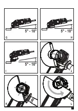
Maintain a 5˚ to 10˚ angle between the tool and work
surface for wire cup brushes as shown in figure I.
u
Maintain contact between the edge of the wheel and the
work surface with wire wheels.
u
Continuously move the tool in a forward and back motion
to avoid creating gouges in the work surface.
Allowing the tool to rest on the work surface without
moving, or moving the tool in a circular motion causes
burning and swirling marks on the work surface.
u
Remove the tool from the work surface before turning the
tool off. Allow the tool to stop rotating before setting it
down.
Warning!
Use extra care when working over an edge, as a
sudden sharp movement of grinder may be experienced.
Mounting and using cutting (type 41) wheels
Cutting wheels include diamond wheels and abrasive discs.
Abrasive cutting wheels for metal and concrete use are
available. Diamond blades for concrete cutting can also be
used.
NOTE:
A closed, 2-sided Type 41 cutting wheel guard is sold
separately and is required when using cutting wheels. Failure
to use proper flange and guard can result in injury resulting
from wheel breakage and wheel contact. Matching diameter
backing flange and threaded clamp nut (included with tool)
must be used for cutting wheels.
Mounting closed (type 41) guard (Fig. J, K, L)
u
Align the three lugs on the guard (7) with the three slots
on the hub. This will align the lugs with slots on the gear
case cover as shown in figure J.
u
Push the guard down until the guard lug engages in the
groove on the gear case hub as shown in figure K.
u
Rotate guard (7) counterclockwise to lock it into place.
The guard body should be positioned between the spindle
and the operator to provide maximum operator protection
as shown in figure L.
u
Tighten the guard latch screw to secure the guard on the
gear case cover. You should be unable to rotate the guard
by hand. Do not operate grinder with a loose guard.
u
To remove the guard, loosen the guard latch screw. Then
rotate the guard so that the three lugs on the guard (7)
align with the three slots on the hub and pull up on the
guard.
Mounting cutting wheels
u
Place the unthreaded backing flange on spindle with the
raised section (pilot) facing up. The raised section (pilot)
on the backing flange will be against the wheel when the
wheel is installed.
u
Place the wheel on the backing flange, centering the
wheel on the raised section (pilot).
u
Install the threaded clamp nut with the raised section
(pilot) facing away from the wheel.
u
Depress the spindle lock button and tighten clamp nut with
included wrench.
u
To remove the wheel, depress the spindle lock button and
loosen the threaded clamp nut with included wrench.
Warning!
Do not use edge grinding/cutting wheels for surface
grinding applications because these wheels are not designed
for side pressures encountered with surface grinding. Wheel
breakage and injury may result.
u
Allow tool to reach full speed before touching tool to work
surface.
u
Apply minimum pressure to work surface, allowing tool to
operate at high speed. Cutting rate is greatest when the
tool operates at high speed.
Summary of Contents for KFBEG110
Page 1: ...www blackanddecker co uk 1 4 2 3 KFBEG110 KFBEG125 ...
Page 2: ...2 13 12 10 3 4 7 5 8 7 6 12 15 14 9 4 4 9 11 12 A B 4 9 10 12 11 A E B C D F ...
Page 3: ...3 G H I J K L ...
Page 14: ...14 ...
Page 15: ...15 ...


