21
ENGLISH
The incorrect installation of the grounding wire connector may result in an
electric shock. If it is necessary to replace or repair both the cable and the
connector, do not connect the grounding wire to the terminal of the flat
blade. The green cable, with or without yellow stripes, is the grounding
cable. In case of doubts regarding the grounding information or whether
the product is properly grounded, make sure you contact a qualified
electrician to verify the connections.
WARNING
6. Important:
A compressor with good dimensions (with pressure
switch) will have roughly six (6) starts per hour. (See Instruction
troubleshooting guide - page 25)
7. Electric Motor Warranty:
The electric motor warranty will only be
granted if the installation instruction are followed according to diagram
(Picture 3 - page 22).
8.
Before plugging the equipment to the electric supply, check if voltage
indicated in the supply wire’s tag matches the local voltage.
Note:
- Th
- Volt
- INS
e energy supply must not present voltage changes o
10%.
age drop caused by start
your safety, the installation must have a grounding conductor
to avoid electric shocks.
TALLATION EXPENSES ARE THE PURCHASER’S
RESPONSIBILITY.
ver ±
- For
up must not be over 10%
CONDUCTOR
(mm)
2
mm
2
AWG
MOTOR
POWER
(HP)
ELECTRICAL
VOLTAGE
(V)
MAX. DIST. (m/inch)
VOLTAGE DROP (%)
FUSE
(A)
35
20
7 / 273
27 / 1053
2,5
1,5
13
15
110/120
220
2.0 MAX.
START UP PROCEDURE
5.2
F
5.3
T
ollow the local technical standards on low voltage electric
installations.
he electric input cables must be in accordance to the motor’s power,
voltage and electrical energy source distance (See Table 2 - for
orientation).
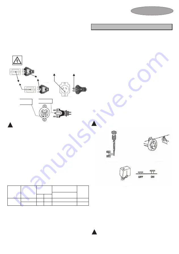
e electric wire with plug as shown in Picture 4: 3 pins (single-
phase). Make sure the outlet has the same configuration as the plug.
Neither adaptors nor a direct conn
ounding instructions:
This product must be grounded
to reduce the risk of an electric shock.
5.4
Th
ection from the power cable to the
switch must be used.
5.5
Gr
This equipment is tested and filled up, in the factory, with coaxial air
compressor lubricant mineral oil.
After the arrangements regarding location, the pressure vase adequacy to
local Technical Norms and Legislation, electric network, the electric outlet
to connect 2P+GR plug, electric switch and (customer’s responsibility)
have all been carried out, do the following:
First start procedure:
6.
Open the valve
13
to discharge the compressed air from the tank and
this will decrease the internal pressure in the compressor. The
compressor will automatically re-start (through the pressure switch)
when the pressure gauge registers 76 psi (5.2 bar).
7.
Close the valve and unplug the equipment turning the button (Picture 8
- OFF).
8.
Open drain
7
(Picture 6) to exhaust the tank’s condensed water and
quickly close it.
1.
Check the oil level, it must be between the maximum and minimum
marks of the oil gauge dipstick
15
(See Picture 5).
2.
Completely open the pressure regulator valve
9.
3.
Turn the start key by pressing the button (Picture 7 - ON).
4.
Let the compressor run for about ten (10) minutes to allow a
homogeneous lubrication of the moving parts.
5.
Fully close the valve
13
, so that the compressor can fill up the tank.
Compressor will automatically turn off (through the pressure switch -
See Picture 7), when the pressure gauge shows maximum pressure
respectively around 116 psi (8.0 bar).
Attention:
The tank’s maximum pressure when drained must
be 10 psi (0.7 bar).
PICTURE 7
9.
Open the valve to completely exhaust the tank and close it
afterwards.
10.
Your
Black&Decker
compressor is now ready to operate. Connect it
to the air distribution network or spiral hose and start the electric
motor. When the compressor reaches maximum pressure, open the
valve so that the air can flow to the distribution network or spiral hose.
Check if there is any leakage along the tubing, by using a water and
soap lather.
Note:
-
The initial start up procedure must be repeated whenever maintenance
occurs.
Attention:
If the compressor’s dimensions are correct the ideal
number of starts is roughly 6 (six) times per hour.
PICTURE 5
PICTURE 6
TABLE 2 - ORIENTATION DATA FOR CONDUCTORS AND FUSES
Grounded
Outlet
Grounding
Pin
PICTURE 4
GROUNDED OUTLET
GROUNDING PIN
GROUNDED
OUTLET
GROUNDING
PIN


