background image

9

ENGLISH

(Original instructions)

The charger may hum and become warm 

while charging; this is normal and does not 

indicate a problem.

Warning! Do not charge the battery at ambi-

ent temperatures below 10 °C or above 40 

°C. Recommended charging temperature: 

approx. 24 °C.

Low battery indicator

When the battery charge becomes low the 

LED work light will begin to flash rapidly.

u

  The LED Flash will last 5 seconds during 

Low voltage - - - - - at this pattern..

Warning! Do not continue using the product 

with its batteries in a depleted condition. 

Recharge discharged batteries promptly..

High temperature indicator

When the circuit operating temperature be-

comes too high the LED work light will begin 

to flash in a long and short pattern.

u

  The LED Flash will last 5 seconds during 

circuit high temperature - . - . - . - . at this 

pattern. Allow the unit to cool down to an 

optimal operating temperature of approxi-

mately 24°C.

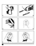
Setting the initial starting point (fig. D)

u

  Grasp the screwdriver as shown in figure 

D.

u

  Press and hold in the motion control 

activator (1) on the back of the tool with 

the palm of your hand.

u

  When the LED work light (4) illuminates 

the tool is ready for use.

u

  To reset initial starting point first release 

the motion control activator (1). Move tool 

to new position, then press and hold in the 

motion control activator (1) on the back of 

the tool with the palm of your hand..

Gyro control callibration

This tool automatically re-calibrates itself 

periodically to ensure correct operation of the 

motion-based  gyro controls. If the contorls do 

not appear to be working corectly the tool can 

be manually callibrated. 

u

  Press the motion control activator (1).

u

  Release the motion control activator (1).

u

  Place the tool on a level surface.

The LED work light (4) will flash twice within 

5 seconds to indicate that the tool has been 

re-calibrated. 

Operating in the forward direction 

(fig. E)

u

  Set the initial starting point.

u

  Rotate the tool clockwise and the screw-

driver will activate in the forward direction.

Note: The speed of the tool is determined by 

the amount of rotation. .

Small rotation = slower speed.

Large rotation = Higher speed.

Operating in the reverse direction 

(fig. F)

u

  Set the initial starting point.

Summary of Contents for BDCS361

Page 1: ...BDCS36G ...

Page 2: ...2 B C D E F A ...

Page 3: ...r tool Distractions can cause you to lose control 2 Electrical safety a Power tool plugs must match the outlet Never modify the plug in any way Do not use any adapter plugs with earthed grounded power tools Unmodified plugs and matching outlets will reduce risk of electric shock b Avoid body contact with earthed or grounded surfaces such as pipes radiators ranges and refrigerators There is an incr...

Page 4: ...enables better control of the power tool in unexpected situations f Dress properly Do not wear loose clothing or jewellery Keep your hair clothing and gloves away from moving parts Loose clothes jewellery or long hair can be caught in moving parts g If devices are provided for the connection of dust extraction and collection facilities ensure these are connected and properly used Use of dust colle...

Page 5: ...tery pack b Use power tools only with specifically designated battery packs Use of any other battery packs may create a risk of injury and fire c When battery pack is not in use keep it away from other metal objects like paper clips coins keys nails screws or other small metal objects that can make a connection from one terminal to another Shorting the battery terminals together may cause burns or...

Page 6: ...ervision or in struction concerning use of the appliance by a person responsible for their safety u Children should be supervised to ensure that they do not play with the appliance Residual risks Additional residual risks may arise when using the tool which may not be included in the enclosed safety warnings These risks can arise from misuse prolonged use etc Even with the application of the relev...

Page 7: ...jury the user must read the instruction manual Additional safety instructions for bat teries and chargers Batteries u Never attempt to open for any reason u Do not expose the battery to water u Do not store in locations where the temperature may exceed 40 C u Charge only at ambient temperatures between 10 C and 40 C u Charge only using the charger provided with the tool u When disposing of batteri...

Page 8: ... tool Fitting and removing a screwdriver bit or socket fig B Warning Make certain the tool is locked to prevent switch actuation before installing or removing accessories u To fit a screwdriver bit push it into the bit holder 2 until it locates u To remove a screwdriver bit pull it straight from the bit holder Note To remove the bit socket repeat the above steps Use Warning Let the tool work at it...

Page 9: ...hold in the motion control activator 1 on the back of the tool with the palm of your hand u When the LED work light 4 illuminates the tool is ready for use u To reset initial starting point first release the motion control activator 1 Move tool to new position then press and hold in the motion control activator 1 on the back of the tool with the palm of your hand Gyro control callibration This too...

Page 10: ... bit in a straight line with the screw Maintenance Your Black Decker tool has been designed to operate over a long period of time with a minimum of maintenance Continuous satisfactory operation depends upon proper tool care and regular cleaning Your charger does not require any mainte nance apart from regular cleaning Warning Before performing any maintenance on the tool remove the battery from th...

Page 11: ...roducts once they have reached the end of their working life To take advantage of this service please return your product to any authorised repair agent who will collect them on our behalf You can check the location of your nearest authorised repair agent by contacting your local Black Decker office at the address indicated in this manual Alternatively a list of authorised Black Decker repair agen...

Page 12: ...45 Screwdriving without impact ah S 2 5 m s2 uncertainty K 1 5 m s2 EC declaration of conformity MACHINERY DIRECTIVE BDCS36G Black Decker declares that these products described under technical data are in compliance with 2006 42 EC EN 60745 1 EN 60745 2 2 These products also comply with Directive 2004 108 EC and 2011 65 EU For more information please contact Black Decker at the following address o...

Page 13: ... u The product has been subjected to misuse or neglect u The product has sustained damage through foreign objects substances or accidents u Repairs have been attempted by persons other than authorised repair agents or Black Decker service staff To claim on the guarantee you will need to submit proof of purchase to the seller or an authorised repair agent You can check the location of your nearest ...

Page 14: ......

Page 15: ... to register your product www blackanddecker co uk productregistration Register your product online at www blackanddecker co uk productregistration or send your name surname and product code to Black Decker in your country ...

Page 16: ...20 5100 20 Fletcher Road Mooroolbark Fax 03 9727 5940 Victoria 3138 New Zealand Black Decker Tel 64 9 259 1133 5 Te Apunga Place Fax 64 9 259 1122 Mt Wellington Auckland 1060 United Kingdom Black Decker Tel 01753 511234 210 Bath Road Fax 01753 551155 Slough Berkshire SL1 3YD ...

Reviews: