


Battery Capacity Analyzer User Manual
24
1. Use the buttons to move the pointer to the desired percent % row and press the button to move the
cursor in the voltage field and enable editing. The and buttons can be used to position the cursor under
the digit to be changed.
2. Use the buttons increment or decrement the digit.
3. When finished editing the digits press the button a few times to return the cursor back to the row and the select
pointer showing.
4. Repeat steps 1 through 3 until all 11 rows have edited.
5. Verify all the 11 rows of enters are correct.
6. Make sure the row pointer is showing and press the button.
If an “Out of Range” is displayed the SOC table was not entered correctly and values must be corrected and reentered.
Note: The SOC Selection is closely related to this section.
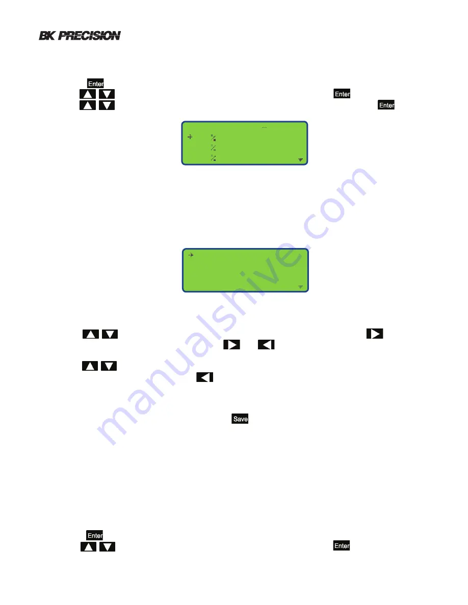
For this example the default row selected, “Setting 12V SOC #1 opening the profile view and edit screen.
Each profile will have 11 rows stating at 100% and ending at 0%.
Setting 12V SOC # 1
Setting 12V SOC # 2
Setting 12V SOC # 3
Setting
6V SOC # 4
View and edit profile
SOC Pro f ile
SOC1
100 = 26 . 214V
90 = 26 . 214V
80 = 26 . 214V
Selecting a profile
1. Power on the 603B.
2. Press the button to select the Main Menu.
3. Use the buttons to move the pointer to the row “System” and press the button.
4. Use the buttons to move the pointer to the row “SOC Profile Settings” and press the button.
The pointer will be located at the row “Setting 12 V SOC #1” by default. The settings continue to the next screen. A total
of 6 profiles can be edited and stored. 3 profiles for both 12 and 6 volt ranges.
4.6.7 SOC Table Selection
This section describes how to set the SOC table used during both Quick Test mode and Database Mode. The 603B is
set to the default SOC tables signified by the letter d for 6 volt and D for 12 volts.
1. Powered on the 603B.
2. Press the button to select the Main Menu.
3. Use the buttons to move the pointer to the row “System” and press the button.


