background image

101 

 
To recall setup data from USB flash drive, follow the steps 
below: 

1.


Press the “SAVE/RECALL” button. 

2.


Press the “Type” button to select “Setups”. 

3.


Insert USB flash drive to USB host port of the 
oscilloscope and wait that the oscilloscope has initialized 
USB flash drive (about five seconds). 

4.


Press the “Save to” option button to select “File”. 

5.


Press the “Save” option button then you’ll go into the 
Save/Recall interface.  

6.


Choose the file you want then press the “Load” option 
button (within 5 seconds there will be a message “Read 
data success”). Now the setup data have been recalled 
from the USB flash drive. 


Recall Factory 

You can use this option to recall the factory settings 

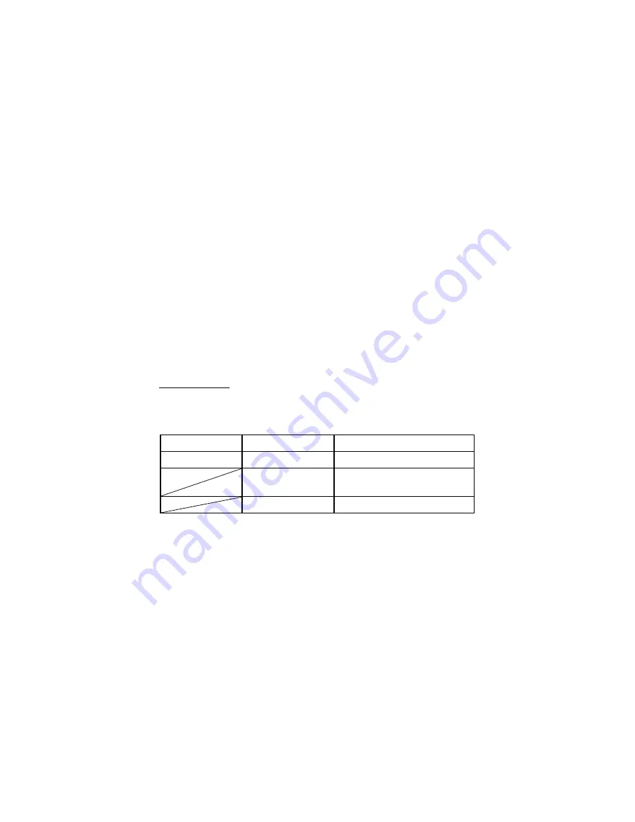
Table 3.45 – Factory Function Menu 

Option 

Setting 

Description 

Type 

Factory 

To view the Factory setup.  


Depth Recover 

Clears all memory, including 
setups, waveforms and masks. 


Load 

Recall the Factory setup. 


www.

GlobalTestSupply

.com

Find Quality Products Online at:

[email protected]

Summary of Contents for 2190E

Page 1: ...Model 2190E 100 MHz Digital Storage Oscilloscope USER MANUAL www GlobalTestSupply com Find Quality Products Online at sales GlobalTestSupply com...

Page 2: ...al violates the safety standards of design manufacture and intended use of the instrument B K Precision assumes no liability for a customer s failure to comply with these requirements Category rating...

Page 3: ...entering a building or other outdoor wiring Do not use this instrument in an electrical environment with a higher category rating than what is specified in this manual for this instrument You must ens...

Page 4: ...nd connection all accessible conductive parts including control knobs may provide an electric shock Failure to use a properly grounded approved outlet and the recommended three conductor AC line power...

Page 5: ...ment is intended to be used in an indoor pollution degree 2 environment The operating temperature range is 0 C to 40 C and the operating humidity is 85 relative humidity at 40 C with no condensation a...

Page 6: ...ust be made by qualified service trained maintenance personnel who are aware of the hazards involved when the instrument s covers and shields are removed Under certain conditions even with the power c...

Page 7: ...are maintained Cooling fans This instrument contains one or more cooling fans For continued safe operation of the instrument the air inlet and exhaust openings for these fans must not be blocked nor m...

Page 8: ...w to the instrument Do not place a hot soldering iron on the instrument Do not pull the instrument with the power cord connected probe or connected test lead Do not move the instrument when a probe is...

Page 9: ...il of the European Union on waste electrical and electronic equipment WEEE and in jurisdictions adopting that Directive is marked as being put on the market after August 13 2005 and should not be disp...

Page 10: ...and 2004 108 EC Electromagnetic Compatibility Directive with the following standards Low Voltage Directive EN61010 1 2001 EN61010 031 2002 A1 2008 EMC Directive EN 61326 1 2006 EN 61000 3 2 2006 A2 2...

Page 11: ...t position of the power switch when instrument is OFF Off Supply This is the AC mains connect disconnect switch on top of the instrument CAUTION indicates a hazardous situation which if not avoided wi...

Page 12: ...ace Description 5 2 Getting Started 6 2 1 Input Power Requirements 6 Input Power 6 2 2 Preliminary Check 6 Verify AC Input Voltage 7 Connect Power 7 Self Test 7 Self Cal 7 Check Model and Firmware Ver...

Page 13: ...ource 48 Trigger Type 49 Coupling 67 Position 67 Slope and Level 68 Trigger Holdoff 69 3 12 Signal Acquisition System 70 3 13 Display System 75 X Y Format 79 3 14 Measure System 80 Scale Measurement 8...

Page 14: ...alyzing Signal Details 139 4 5 Triggering on a Video Signal 140 4 6 Application of X Y Function 141 4 7 Analyzing a Differential Communication Signal 143 5 Remote Control 144 6 Message Prompts and Tro...

Page 15: ...gger types Edge Pulse Video Slope and Alternative Digital filter and waveform recorder functions Automatic measurement of 32 parameters Voltage and Time Standard USB host USBTMC device and LAN ports 1...

Page 16: ...front panel before operating the instrument Below is a brief introduction of the front panel function operation Figure 1 1 Front Panel Front Panel Description Front USB Type A Connector Menu Function...

Page 17: ...and Measurement Buttons Universal Knob Vertical Controls 1 4 Back Panel The following images show back and side panel connection locations Figure 1 2 Back Panel 1 2 3 5 6 4 6 10 9 5 7 8 www GlobalTes...

Page 18: ...LAN Interface Pass Fail Output Rear USB Type B Device Connector Power Input Connector AC Power Switch 1 5 Display Information Figure 1 3 Display Screen 1 2 3 4 5 6 www GlobalTestSupply com Find Quali...

Page 19: ...r Menu Trigger Source Type and Level Indicator Frequency Counter Horizontal Delay Position Horizontal Time Base Setting Channel Source Coupling Type Volts Division BW Limit Indicator Vertical Display...

Page 20: ...wer cord including the extension line is compatible with the rated voltage current and that there is sufficient circuit capacity for the power supply Once verified connect the cable firmly The include...

Page 21: ...fter which the main screen will be displayed Self Test The instrument has 3 self test options to test the screen keys and the LED back lights of the function menu and channel keys as shown below Figur...

Page 22: ...s functionality 1 Power on the oscilloscope Press DEFAULT SETUP to show the result of the self check The probe default attenuation is 1X Figure 2 2 Scope Layout 2 Set the switch to 1X on the probe an...

Page 23: ...peak square wave in couple seconds Figure 2 4 3 Vpp Square Wave 4 Press CH1 two times to turn off channel 1 Press CH2 to change screen into channel 2 reset the channel 2 as step 2 and step 3 PROBE CO...

Page 24: ...ents SHOCK HAZARD To avoid electric shock when using the probe keep fingers behind the guard on the probe body To avoid electric shock while using the probe do not touch metallic portions of the probe...

Page 25: ...ing for the Probe option is 1X Be sure that the attenuation switch on the probe matches the Probe option in the oscilloscope Switch settings are 1X and 10X NOTE When the attenuation switch is set to 1...

Page 26: ...ly inserting the tip onto the probe 2 Attach the probe tip to the PROBE COMP 3V connector and the reference lead to the PROBE COMP Ground connector Display the channel and then push the AUTO button 3...

Page 27: ...button Connector Auto Setup Default Setup Universal knob Vertical System Channel Function Menu Math Functions Using REF Horizontal System Trigger System Acquiring signals System Display System Measur...

Page 28: ...menu to set up a channel When the channel is on the channel button is lit MATH Press to display the Math menu You can use the MATH menu to use the oscilloscope s Math functions REF Press to display t...

Page 29: ...20 oscilloscope setups and 10 waveforms to from internal memory or a USB memory device limited by memory capacity of the USB flash drive You can also use it to recall the default factory settings to s...

Page 30: ...pped using the RUN STOP or SINGLE button the TIME DIV control expands or compresses the waveform SINGLE Acquire a single waveform and then stops waveform acquisition 3 2 Connectors Figure 3 2 Connecto...

Page 31: ...ress the AUTO front panel button and then press the menu option button adjacent to the desired waveform as follows Figure 3 3 Auto Setup Table 3 1 Autoset Menu Option Description Multi cycle sine Auto...

Page 32: ...lowest numbered channel displayed when Auto set was invoked No signals found and no channels displayed oscilloscope displays and uses channel 1 Table 3 2 Auto Set Function Menu Items Function Setting...

Page 33: ...button can be disabled Please see Education Mode for details 3 4 Default Setup The oscilloscope is set up for normal operation when it is shipped from the factory This is the default setup To recall...

Page 34: ...DC BW limit Off Volts div Coarse Probe 1X Invert Off Filter Off Volts div 1 00V MATH Operation CH1 CH2 CH1 Invert Off CH2 Invert Off FFT operation Source CH1 Window Hanning FFT Zoom 1X Scale dBVrms Di...

Page 35: ...d Intensity 60 Brightness 40 Format YT Menu Display infinite SAVE RECALL Type Setups Save To Device Setup No 1 REF REFA REFB REFA Source CH1 REFA off REFB off UTILITY Sound on Counter On Back USB USBT...

Page 36: ...g DC TRIGGER Video Type Video Source CH1 Polarity Normal Sync All Lines Standard NTSC Mode Auto TRIGGER Slope Type Slope Source CH1 Time 1 00ms Mode Auto TRIGGER Alternative Type Alternative Source CH...

Page 37: ...b to adjust the storage position of setups waveforms pictures when saving recalling and to select menu options With some functions the light indicator above the knob will turn on to indicate that the...

Page 38: ...of the screen For example Volts Pos 24 6mV 3 Press the vertical POSITION knob to set the vertical position to zero Volts div Knob 1 Use the Volts div knobs to control how the oscilloscope amplifies o...

Page 39: ...ng Introduction Coupling DC AC GND DC passes both AC and DC components of the input signal AC blocks the DC component of the input signal and attenuates signals below 10 Hz GND disconnects the input s...

Page 40: ...rn off invert function Filter Press this button to enter the Digital Filter menu Next Page Page 2 3 Press this button to enter the third page menu Table 3 6 Channel Function Menu 3 Option Setting Intr...

Page 41: ...aveform Internally the channel input is connected to a zero volt reference level Fine Resolution The vertical scale readout displays the actual Volts Div setting while in the fine resolution setting C...

Page 42: ...Setting up Channels Each channel has its own separate Menu The items are set up separately according to each channel 1 Setup Channel Coupling Take CH1 for example the tested signal is a sine wave sign...

Page 43: ...sconnects the input signal 2 Bandwidth Limiting Take CH1 for example Press CH1 BW Limit On and bandwidth will be limited to 20 MHz Press CH1 BW Limit Off and bandwidth limit will be disabled www Globa...

Page 44: ...ult setting of Volts Div and makes the vertical scaling in a 1 2 5 step sequence from 2 mV div 5 mV div and 10 mV div to 10 V div Press CH1 Volts Div Fine This setting changes the vertical control to...

Page 45: ...the channel operation Menu If the attenuation coefficient is 10 1 the input coefficient should be set to 10X so that the Volts div information and measurement testing is correct Take CH1 for example w...

Page 46: ...Attenuation Setting 5 Inverting Waveforms Take CH1 for example Press CH1 Next Page Page 1 3 Invert On Figure 3 10 Invert Waveform Screen www GlobalTestSupply com Find Quality Products Online at sales...

Page 47: ...r Limit or Lower Limit and turn the Universal knob to adjust them Press CH1 Next Page Page 1 3 Filter Off Turn off the Digital Filter function Figure 3 11 Digital Filter Menu Press CH1 Next Page Page...

Page 48: ...Press the MATH button again to remove the math waveform display Table 3 8 Math Function Menu Function Setting Description Operation FFT Math operates between signal source CH1 and CH2 Source A CH1 CH2...

Page 49: ...ust the vertical scale of the MATH waveform Next Page Page 2 2 Go back to first page of MATH menu Table 3 10 Math Function Description Operation Setting Description A B Source A waveform adds Source B...

Page 50: ...als Analyze the harmonic wave in the Power cable Test the harmonic content and distortion in the system Show the Noise in the DC Power supply Test the filter and pulse response in the system Analyze v...

Page 51: ...u Table 3 12 FFT Function Menu 2 FFT Option Setting Description Scale Vrms Set Vrms to be the Vertical Scale unit dBVrms Set dBVrms to be the vertical Scale unit Display Split Full screen Display FFT...

Page 52: ...cope to display many signal cycles To display FFT correctly follow these steps 1 Push the MATH button 2 Set the Operation option to FFT 3 Press the Source button to select CH1 or CH2 according to inpu...

Page 53: ...d points to be at different amplitudes The transitions between the start and end points cause discontinuities in the signal that introduce high frequency transients Table 3 13 FFT Window Description W...

Page 54: ...horizontally in a 1 2 5 step To magnify vertically turn the Volts div knob Measuring an FFT Spectrum Using Cursors You can take two measurements on FFT spectrums magnitude in dB and frequency in Hz Ma...

Page 55: ...button to select MATH 12 Press the CurA option button turn the Universal knob to move Cursor A to the highest point of the FFT waveform 13 Press the CurB option button turn the Universal knob to move...

Page 56: ...t has a DC component or offset can cause incorrect FFT waveform magnitude values To minimize the DC component choose AC Coupling on the source waveform To display FFT waveforms with a large dynamic ra...

Page 57: ...eform has been saved Table 3 14 REF Function Menu Option Setting Description Source CH1 CH2 CH1 off CH2 off Choose the waveform display to store REFA REFB Choose the reference location to store or rec...

Page 58: ...Volts div knob to adjust the vertical position and scale 4 Press the third option button to select REFA or REFB as storage position 5 Press the Save option button 6 Press the bottom option button to...

Page 59: ...reen and window time base waveform to display on the below half screen at the same time Turn off this function to only display main time base waveform on the screen Horizontal Control Knob You can use...

Page 60: ...t changes the width of the window zone by changing the window time base Display scan mode When the Time div control is set to 100 ms div or slower and the trigger mode is set to Auto the oscilloscope...

Page 61: ...ed window waveform display on the below half screen at the same time 3 11 Trigger System The trigger determines when the oscilloscope starts to acquire data and display a waveform When a trigger is se...

Page 62: ...ls automatically This is useful when you connect a signal to the EXT TRIG BNC and set the trigger source to Ext or Ext 5 FORCE Button Use the FORCE button to complete the current waveform acquisition...

Page 63: ...EXT Does not display the trigger signal the Ext option uses the signal connected to the EXT TRIG front panel BNC and allows a trigger level range of 1 2V to 1 2V EXT 5 Same as Ext option but attenuat...

Page 64: ...oscilloscope to acquire a single waveform press the SINGLE button Set up Enter the Trigger Setup Menu See Table 3 17 Table 3 17 Trigger Setup Function Menu Option Setting Explain Coupling DC Passes al...

Page 65: ...RIG MENU button to display Trigger menu Press the Type option button to select Edge 2 Set up Source According to the input signal press the Source option button to select CH1 CH2 EXT EXT 5 or AC Line...

Page 66: ...waveform when the trigger condition is satisfied and then stops 5 Set up Trigger coupling Press the Set Up button to enter the Trigger Setup Menu Press the Coupling option button to select DC AC HF R...

Page 67: ...pulse width setting Negative pulse width equal to pulse width setting Select how to compare the trigger pulse relative to the value selected in the Set Pulse Width option Set Width 20 0ns 10 0s Selec...

Page 68: ...ype of triggering Normal mode is best for most Pulse Width trigger applications Set up Enter the Trigger setup menu Next Page Page 2 2 Press this button to return to the first page Figure 3 23 Pulse T...

Page 69: ...AC then you could trigger the NTSC PAL and SECAM video signal Source CH1 CH2 Select the input source to be the trigger signal EXT EXT 5 Ext and Ext 5 use the signal applied to the EXT TRIG connector...

Page 70: ...a valid trigger This mode allows an untriggered scanning waveform at 100 ms div or slower time base settings Normal Use this mode when you want to see only valid triggered waveforms when you use this...

Page 71: ...tton to select or 3 Set up Synchronization Press the Sync option button to select All Lines Line Num Odd Field and Even Field If you select Line Num you can turn the Universal knob to set the appointe...

Page 72: ...e Trigger on positive slope of negative slope according to setup time of the oscilloscope Source CH1 CH2 EXT EXT 5 Select trigger source When Select trigger condition Time Set time Turn the Universal...

Page 73: ...e trigger level that can be adjusted by LEVEL knob You can adjust LEVEL A LEVEL B or adjust them at the same time Mode Auto Use this mode to let the acquisition free run in the absence of a valid trig...

Page 74: ...form press the SINGLE button Set up Enter Trigger setup menu See Table 3 17 Next Page Page 2 2 Return to the first page of slope trigger Figure 3 26 Slope Trigger Menu 2 Operating Instructions Follow...

Page 75: ...t trigger level that can be adjusted 10 Turn the LEVEL knob Alternate Trigger The trigger signal comes from two vertical channels when you use alternate trigger In this mode you can observe two irrela...

Page 76: ...trigger type information for CH2 signal Mode Edge Set trigger type of vertical channel signal to edge Next Page Page 1 2 Go to the second page of the TRIGGER Menu Table 3 24 Alternate Trigger Edge Mod...

Page 77: ...Set trigger type information for CH2 signal Mode Pulse Set trigger type of the vertical channel signal to Pulse trigger Next Page Page 1 2 Enter the second page of Alternative trigger menu Table 3 26...

Page 78: ...H1 CH2 Set the trigger channels Source CH1 CH2 Set trigger type information for CH1 signal Set trigger type information for CH2 signal Mode Video Set trigger type of the vertical channel signal to Vid...

Page 79: ...iption Type Alternative The trigger signal comes from two vertical channels when you use alternative trigger In this mode you can observe two irrelative signals at the same time Channels CH1 CH2 Set t...

Page 80: ...t the same time Set up Enter Trigger setup menu See Table 3 17 Next Page Page 2 2 Return to the first page of Alternative trigger menu Operating Instructions To use alternate triggering follow these s...

Page 81: ...veform If you use trigger coupling you should press the TRIG MENU button and then select Edge Pulse Video or Slope trigger Then select the Coupling option in the Set Up menu Position The horizontal po...

Page 82: ...NGLE button when you want the oscilloscope to acquire a single waveform Trigger coupling affects only the signal passed to the trigger system It does not affect the bandwidth or coupling of the signal...

Page 83: ...me Trigger position Trigger level Figure 3 29 Trigger Holdoff Illustration If you want to change holdoff time please follow the steps below 1 Press the TRIG MENU button to show the TRIG Menu 2 Press t...

Page 84: ...lation Mode Equ time Real time Set the Sampling mode to Equivalent time Set the Sampling mode to Real time Sa Rate Displays system sampling rate When you acquire a signal the oscilloscope converts it...

Page 85: ...Figure 3 30 Acquire Menu Peak Detect Peak Detect mode capture the maximum and minimum values of a signal Finds highest and lowest record points over many acquisitions Advantage In this way the oscillo...

Page 86: ...The oscilloscope acquires several waveforms averages them and displays the resulting waveform Advantage You can use this mode to reduce random noise www GlobalTestSupply com Find Quality Products Onl...

Page 87: ...button again to stop the acquisition SINGLE Button Press the SINGLE button to acquire a single waveform Each time you push the SINGLE button the oscilloscope begins to acquire another waveform After...

Page 88: ...t sample the signal fast enough to construct an accurate waveform record When this happens the oscilloscope displays a waveform with a frequency lower than the actual input waveform or triggers and di...

Page 89: ...em The display function can be setup by pressing the DISPLAY button Table 3 32 Display System Menu 1 Option Setting Description Type Vectors Dots Vectors fill the space between adjacent sample points...

Page 90: ...mat displays a dot each time a sample is acquired on channel 1 and channel 2 Screen Normal Inverted Set to normal mode Set to invert color display mode Grid Display grids and axes on the screen Turn o...

Page 91: ...Table 3 34 Display System Menu 3 Option Setting Description Skin Classical Modern Tradition Succinct Set up screen style Next Page Page 3 3 Press this button to return to the first page Operating Ins...

Page 92: ...ensity option button and turn the Universal knob to adjust waveforms intensity Set up Brightness Press the Brightness option button and turn the Universal knob to adjust grid brightness Set up display...

Page 93: ...nnel 2 is the vertical axis The oscilloscope uses the untriggered Sample acquisition mode and displays data as dots NOTE The oscilloscope can capture a waveform in normal YT mode at any sampling rate...

Page 94: ...orm amplitude and determine that it is a little more than 100 mV You can take simple measurements by counting the major and minor graticule divisions involved and multiplying by the scale factor For e...

Page 95: ...sure voltage or time You can move the cursor by turning the Universal knob Before using cursors you should make sure that you have set the signal source as the channel for measuring Voltage Cursor Vol...

Page 96: ...urn the Universal knob to adjust Cursor B 7 The measurement values are displayed on the top of the left corner If the measurement type is set to Voltage the values are as followed The voltage incremen...

Page 97: ...nal channel that the Cursor A will measure Cursor B CH1 CH2 NONE Set the input signal channel that the Cursor B will measure Cur A Select this option turn the Universal knob to adjust horizontal coord...

Page 98: ...Cur A turn the Universal knob to move Cursor A horizontally 6 Select Cur B turn the Universal knob to move Cursor B horizontally 7 The measurement values are displayed on the top left of the screen A...

Page 99: ...automatically These cursors demonstrate the physical meanings of these measurements To do auto cursor measurements follow these steps 1 Press the CURSOR button to enter Cursor measure menu 2 Press th...

Page 100: ...asurements are confined to be made by only using points on the display and not all the data points recorded by the oscilloscope Press the MEASURE button for Automatic Test There are three auto measure...

Page 101: ...measure menu Figure 3 40 Auto Measure Menu Table 3 38 Auto Voltage Measurement Menu Option Setting Description Source CH1 CH2 Select input signal source for Voltage measure Type Vpp Vmax Vmin Vpp Vamp...

Page 102: ...CH2 Select input signal source for Time measure Type Period Freq Width Width Rise Time Fall Time BWidth Duty Duty Press the Type button or turn the Universal knob to select Time measure parameter Dis...

Page 103: ...e 3 41 All Measurement Menu Option Setting Description Source CH1 CH2 Select input signal channel Voltage On Off Turn on the all measurement function to measure voltage parameters Turn of the all meas...

Page 104: ...sures the lowest voltage over the entire waveform Vamp Voltage between Vhig and Vlow of a waveform Vavg The arithmetic mean over the first cycle in the waveform Mean The arithmetic mean over the entir...

Page 105: ...50 level Duty Measures the first cycle waveform Positive Duty Cycle is the ratio between positive pulse width and period Duty Measures the first cycle waveform Negative Duty Cycle is the ratio between...

Page 106: ...of source Y If you want to measure voltage parameters please follow the steps below 1 Press the MEASURE button to enter the Auto measurement menu 2 Press the first option button to enter the second m...

Page 107: ...me If you want to measure time parameters using all measure function please follow these steps 1 Press the MEASURE button to enter the Auto Measure menu 2 Press the top option button to enter the seco...

Page 108: ...you can save setup data waveform data waveform display image and CSV file to a USB flash drive Setup data and waveform data that are saved to a USB flash drive can be recalled on the oscilloscope For...

Page 109: ...3 43 Save All Menu Directory While file shows option buttons for New File Delete File and Load Figure 3 44 Save All Menu Files www GlobalTestSupply com Find Quality Products Online at sales GlobalTest...

Page 110: ...grayed out when BMP or CSV file types are selected Both Directory and Files have Rename and Return option buttons on Page 2 2 Use these buttons to give an existing folder of file a new name or to exit...

Page 111: ...ld completed as desired to save the file onto the memory device After the Confirm option button is pressed a Data Store Success messages briefly shown and the new folder or file is shown on your USB f...

Page 112: ...e s internal memory follow the steps below For example Save setup that set waveform display type to Dots to internal memory 1 Press the SAVE RECALL button to enter the SAVE RECALL menu 2 Press the Typ...

Page 113: ...ct Setups 3 Press the Save to option button to select Device 4 Press the Setup option button or turn the Universal knob to select No 1 5 Press the Recall option button Save Setup to USB flash drive Ta...

Page 114: ...ve option button then you ll go into the Save Recall interface 5 Press the New Dir button to create a new folder 6 Press the Del folder option button to delete a folder 7 Press the New file option but...

Page 115: ...ll go into the Save Recall interface 6 Choose the file you want then press the Load option button within 5 seconds there will be a message Read data success Now the setup data have been recalled from...

Page 116: ...alling Save to Device Save waveforms to the oscilloscope s internal memory Waveform No 1 to No 10 Press the waveform option button or turn the Universal knob to select storage location Save Save wavef...

Page 117: ...tion button or turn the Universal knob to select No 1 6 Turn the Volts div knob or Time div knob to adjust the waveform that you want 7 Press the Save option button To recall waveforms follow the step...

Page 118: ...drive Save Select to save to USB Figure 3 50 Save Waveform Screen To Flash Drive To save waveforms to a USB flash drive follow the steps below 1 Input a sine signal to channel 1 press the AUTO button...

Page 119: ...drive to the front or rear USB host port of the oscilloscope and wait until the oscilloscope has initialized USB flash drive within ten seconds 4 Press the Save to option button to select File 5 Pres...

Page 120: ...ait until the oscilloscope has initialized the USB flash drive about five seconds 5 Press the Print Key option button to save the screenshot image to the USB flash drive 6 Alternatively you can custom...

Page 121: ...he Storage CSV file to USB flash drive Data Depth Displayed Maximum Set to store displayed waveform data to CSV file Set to store maximum waveform data to CSV file Para Save On Off Set whether to incl...

Page 122: ...SB flash drive about five seconds 4 Press the Data Depth option button to select Displayed or Maximum 5 Press the Para Save option button to select On or Off 6 Press the Save option button then you ll...

Page 123: ...ata depth set to maximum Time Base Single Channel Dual Channel 2 5 ns 50 ns 40 k 20 k 100 ns 50 ms 20 k 20 k 3 16 Utility System Press the UTILITY button from the front panel to access utility options...

Page 124: ...m Menu 2 Option Setting Description Do Self Cal Auto self emendation Do Self Test Screen Test Keyboard Test LED Test Run the screen test program Run the keyboard test program Run the LED test program...

Page 125: ...irmware of the oscilloscope using a USB flash Drive Pass Fail Press this button to enter the Pass Fail menu Record Press this button to enter the waveform record menu IO Setting Press this button to s...

Page 126: ...escription Screen saver 1min 2min 5min 10min 15min 30min 1hour 2hour 5hour Off Set the time of Screen saver Recorder Enter recorder function scan mode only Next Page Press this button to enter first p...

Page 127: ...Screen 4 System Status Press the System Status option button of the Utility Menu to view the oscilloscope s hardware and software configuration www GlobalTestSupply com Find Quality Products Online a...

Page 128: ...the software version Hardware Version List the hardware version Product type List the product model Serial No List the product serial number Language Menu items can be displayed in 12 different langu...

Page 129: ...ment runs more than thirty minutes running self calibration is recommended When you run the self Calibration you must disconnect all the probes and leads and make sure the scope is not in Single Shot...

Page 130: ...rd Test Run Keyboard Test Program LED Test Run LED Test Program Screen Test Select Screen Test to enter the screen test interface The message Press SINGLE Key to continue Press RUN STOP Key to exit is...

Page 131: ...eys and knobs to verify that all the backlit buttons illuminate correctly NOTE When you first enter the test the screen will display all on screen shapes in white color Pressing any buttons on the fro...

Page 132: ...Press RUN STOP Key to exit Each time SINGLE key is pressed a key shape on the screen will turn green indicating that the corresponding key or indicator should be lid up Press SINGLE again to test anot...

Page 133: ...l of the oscilloscope 3 Press the UTILITY button to enter the Utility menu 4 Press the Next Page option button to enter the third page of the Utility menu 5 Press the Update Firmware option button Rea...

Page 134: ...signals and output pass or fail signals by monitoring the input signal and checking if it is within the predefined mask or not Table 3 56 Pass Fail Menu 1 Option Setting Description Enable On Off Turn...

Page 135: ...l when fail condition is detected Stop On Output On Off When On stops test when output occurs When Off continues test when output occurs Mask Setting Enter the Mask Setting menu Return Return to the P...

Page 136: ...iv 4 00div Y Mask ydiv Turn the Universal knob to set the range of vertical clearance to the waveform 0 04div 4 00div Create Mask Create a test mask according to the above clearance Location Internal...

Page 137: ...ting Description Save Store created mask setting Load Recall stored mask setting Return Return to the main menu of mask setting Last Page Page 2 2 Return to the first page of Mask Setting menu www Glo...

Page 138: ...ource option button to select input signal channel 7 Press the Next Page Page 1 2 option button to enter the second page of the Pass Fail menu 8 Press the Mask Setting option button to enter the first...

Page 139: ...est output especially useful when capturing abnormal signals over a long period of time without having to watch the signal Table 3 60 Waveform Record Function Menu Option Setting Description Mode Reco...

Page 140: ...n button to select Record 5 Press the Source option button to select the input signal channel 6 Select Interval option and turn the Universal knob to adjust time interval between record frames 7 Selec...

Page 141: ...r play mode Set single time play mode Interval Set time interval between frames Next Page Page 1 2 Enter the second page of Play Back menu Figure 3 68 Playback Menu Screen 1 Recode Mode Table 3 62 Wav...

Page 142: ...ton to enter Utility menu 2 Press the Mode option button to select Play Back 3 Press the Play Mode option button to select or 4 Press the Interval option button to select time interval between play ba...

Page 143: ...izontal Control Knob section It is similar to the above described waveform recorder mode however the recorded data can be played back on screen and be retrieved from storage memory Maximum recordable...

Page 144: ...e Memory USB key Stores recording to internal memory Stores recording to external USB flash drive Return Return to the Recorder Menu Table 3 65 Waveform Recorder Replay Mode Menu Option Description Co...

Page 145: ...een recording and channel recalling Waveform of recording on split screen and channel recalling CH1 is displayed in upper half screen and CH2 is displayed in lower half screen Record Mode Roll Single...

Page 146: ...e UTILITY button to enter Utility menu 2 Press the Next Page option button to enter the fourth page of Utility menu 3 Press the Recorder button to enter the Recorder menu 4 Press the Option button to...

Page 147: ...picture below Figure 3 73 LAN Configuration Note To move to the right press the Universal Button To change the values of the menus rotate the Universal Button and finally to jump to the next line pre...

Page 148: ...the HELP button to enter the help status and then press any button to recall the corresponding help information All submenus of every main menu have their help information NOTE If you want to see hel...

Page 149: ...rcuit display the signal quickly and measure the frequency and peak to peak amplitude Using Auto set To quickly display a signal follow these steps 1 Press the CH1 button set the Probe option attenuat...

Page 150: ...and measure value will display on the third option area Measure signal frequency 1 Press the MEASURE button to display Auto Measure Menu 2 Press the top second option button 3 Press the Voltage option...

Page 151: ...easured ring frequency on the top left of the screen Figure 4 1 Taking Cursor Measurements Time Measuring Ring Amplitude To measure the amplitude follow these steps 1 Press the CURSORS button to see t...

Page 152: ...t Cursor B Figure 4 2 Taking Cursor Measurements Voltage 4 3 Capturing a Single Shot Signal To capture a single event you need to gather some knowledge of the signal in order to correctly set up the t...

Page 153: ...with one acquisition Pressing the RUN STOP button again rearms the trigger circuit and erases the display 4 4 Analyzing Signal Details You have a noisy signal displayed on the oscilloscope and need t...

Page 154: ...f a signal 4 5 Triggering on a Video Signal Observe the video circuit in a piece of medical equipment and use the video trigger to obtain a stable display Triggering on Video Field To trigger on the v...

Page 155: ...circuit To view the input and output of the circuit in an XY display follow these steps 1 Press the CH 1 MENU button and set the Probe option attenuation to 10X 2 Press the CH 2 MENU button and set th...

Page 156: ...and turn the Universal knob to adjust the contrast of the screen Apply the Ellipse method to observe the phase difference between the two channels D C A B signal must be centered in X Figure 4 3 Out o...

Page 157: ...be in the range of 2 or 3 2 4 7 Analyzing a Differential Communication Signal You are having intermittent problems with a serial data communication link and suspect poor signal quality Set up the osci...

Page 158: ...nel 2 waveforms from the display ii Turn the CH 1 and CH 2 VOLTS DIV and VERTICAL POSITION knobs to adjust the vertical scale and position NOTE First be sure to compensate both probes Differences in p...

Page 159: ...145 Remote communication commands are supported via the USB and LAN interface www GlobalTestSupply com Find Quality Products Online at sales GlobalTestSupply com...

Page 160: ...unning No signal The system would display this information when the signal could not match the auto set condition while using the auto set function Adjust at limit Prompts that the pulse width setting...

Page 161: ...signal wave in the screen after probing DUT for a signal please do as follows 1 Check whether the probe is connecting with the signal cable or not 2 Check whether the signal cable is connected with t...

Page 162: ...ve the trigger level to the middle position or set the trigger mode to the Auto position You can also press the Auto button to set it up automatically 6 After the Acquisition is set to Averages or Dis...

Page 163: ...hin the factory calibration interval All specifications are guaranteed unless noted typical 2190E Inputs Input Coupling AC DC GND Input Impedance 1 M 2 16 pF 3 pF Maximum Input voltage 400 V DC AC PK...

Page 164: ...ut w 50 feed thru Math operation FFT FFT Window mode Hanning Hamming Blackman Rectangular Sampling points 1024 Bandwidth limited 20 MHz 40 Note Bandwidth limited below 20 MHz when using probe in x1 Ho...

Page 165: ...ory depth 2 sampling Delay Trigger 271 04 div Trigger Level Accuracy typical applicable for the signal of rising and falling time 20 ns Internal 0 2 div V div within 4 divisions from center of screen...

Page 166: ...igger Position Save Recall 20 setups and 10 captured waveforms to from internal memory or to external USB flash drive Measurement System Measure 32 Types Vpp Vmax Vmin Vamp Vtop Vbase Vavg Mean Crms V...

Page 167: ...to 60 Cooling Cooling Fan Humidity Operating 85 RH 40 24 hours Not operating 85 RH 65 24 hours Altitude Operating 3000m Not operating 15 266m AC Input 100 240 VAC CAT II Auto selection Frequency 45 H...

Reviews: