Griven AL2320, Instruction Manual
The Griven AL2320 is a revolutionary lighting fixture, designed to captivate any environment with its stunning visual effects. Enhance your space effortlessly with this versatile product. Instruction Manual available for download, free of charge, on our website. Simply visit manualshive.com and unlock the full potential of your AL2320.
Share
Download


Reviews:
No comments
Related manuals for AL2320

963
Brand: MacDon Pages: 89

903
Brand: Yates Pages: 2

Mini
Brand: Parata Pages: 40

H5000 Pilot
Brand: B&G Pages: 3

SE100
Brand: JBSYSTEMS Light Pages: 17

ST70 Instrument
Brand: Raymarine Pages: 12

SmarTrax
Brand: Raven Pages: 73

DA-40
Brand: Tascam Pages: 3
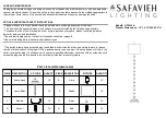
Aurelia
Brand: Safavieh Lighting Pages: 2

SR2
Brand: RAB Lighting Pages: 4

Raiju
Brand: campgo Pages: 33

Tamora Plus II
Brand: Ultimate Healthcare Pages: 2

Cura II
Brand: Ultimate Healthcare Pages: 40

2261998USBA1-XX
Brand: MMF POS Pages: 5

Aqua Timer 3000
Brand: Melnor Pages: 6

ADB KLEMANTIS AS 1000
Brand: Osram Pages: 24

STS 6030
Brand: Axi Pages: 27

DGF100
Brand: Ground Fault Systems Pages: 26


