


M
O
WAY
Title
: mOway Beginner Manual
Rev
: v2.1.3 – March 2011
Page
9
of
65
www.moway-robot.com
3.2.
Drive system
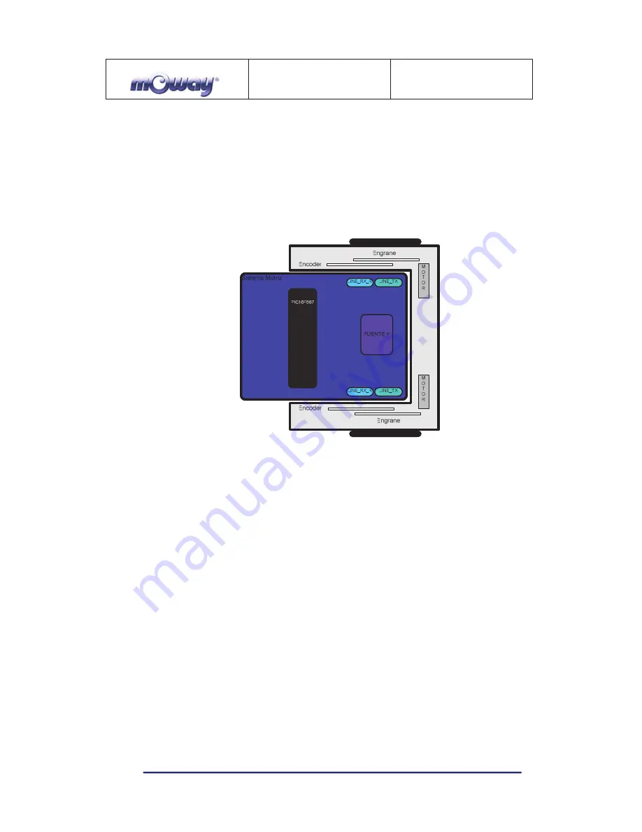
To be able to move the mOway uses a double servo-motor group. It includes both
an electronic part and a mechanical one. The electronic part is mainly in charge of
controlling the motor’s speed and the mechanical part allow the mOway to move
unhindered over different terrains with adequate power.
Image 2. Drive system: electronic and mechanical
The servo-motor group includes different features:
1.
Speed control
: controls the speed of each motor.
2.
Time control
: controls the time for each command with a 100 ms precision.
3.
Traveled distance control
: Controls the distance traveled by each command
with a precision of 1 mm aprox.
4.
General speedometer
: counts distances traveled since the initial command.
5.
Angle control
: controls the angle when the mOway rotates.
The microcontroller sends the I2C command to the drive system that controls the
motors and therefore releasing the main microcontroller so it can carry out other tasks.
Speed control is carried out by means of proportional control with negative
feedback from the encoders’ signal. The illustration displays the controlling system. The
microcontroller feeds the motors through an H bridge controlled by pulse width
modulation (PWM) signals. Wheel rotation is monitored by an encoding sticker and an
infrared sensor. When the sticker shows its black segment, the logical output shall be 1
and when it shows the white sector the output shall be 0. The microcontroller analyzes
these signals (it can determine the exact wheel speed by measuring the pulse width) and