


CT-110-2
8
4.1
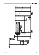
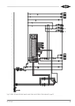
Dimensional drawing SE-i1
R
Please see manual for complete data.
L1:Black
L2:Brown
L3:Blue
Operation
W
arning
Service
COM3
NC
NO
C
N
L
PE
Relay
Fault
Comm.
COM2
Not in use
Signal
GND
+24V Supply
GND
Signal
GND
PTC-1
PTC-2
Signal
GND
Signal
GND
+5V Supply
Signal
GND
+5V Supply
Signal
GND
+24V Supply
DATA+
DATA-
GND
Oil flow
Mot.
PTC
Toil/
Tdis
OLC/
Oil stop
Taux
Pdis
Psuc
1
4
8
10
12
14
17
20
Supply
Control
DATA+
DATA-
GND
COM1
134
11
90
53
142
34
45
3
11
4
6
Fig. 2: Dimensional drawing SE-i1
5
Mounting and activation of the completion sensor kit
WARNING
The compressor is under pressure!
Serious injuries are possible.
Depressurize the compressor!
Wear safety goggles!
5.1
Mounting the components of the completion
sensor kit to CS. compressors
The wired and connected CS. screw compressors, ex-
cept for CSHP compressors, can be ordered ex factory
either with the SE-i1 basic sensor kit or with the full
sensor kit. Scope of functions, see chapter Monitoring
functions, protective functions and extent of delivery,
page 4.
Therefore, all components of the completion sensor kit
must be mounted to the compressor only if:
• the basic sensor kit is to be upgraded to the full func-
tionality of the full sensor kit.
Summary of Contents for SE-i1
Page 54: ...Notes...
Page 55: ...Notes...