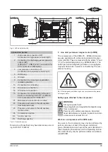
background image

KB-120-8

30

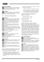
WARNING

Induction, electric voltage!
Never operate the motor with the terminal box
open!

When the rotor rotates, electric voltage is induced in
the terminal pins – even with the motor switched off.

Permitted work on a compressor with LSPM motor

Work on the electric connection and screwed connec-
tions in the terminal box, oil change as well as inspec-
tion and replacement of pressure relief valves, cylinder
banks and sight glass. No special tools are needed for
this work. Before opening the compressor, thoroughly
clean its environment. Pay special attention to loose
metal particles! Do not open the motor cover!

6

Commissioning

Information

General information and requirements, see op-
erating instructions KB-104.

Before commissioning the system, check all safety and
monitoring devices of the system and in the machine
room for correct functioning.

The following information must also be available:

• Design parameters.

• Maximum allowable pressures at standstill and dur-

ing operation.

• Pipelines and instruments diagram.

Information

Special care is required when commissioning
CO

2

 cascade systems.

Due to the high solubility of refrigerant in oil, the
high pressure levels and possibly strong pres-
sure variations after the starting process, there
is a risk of overstress and lack of lubrication.
It is therefore necessary to observe thoroughly
the working behaviour and the operating condi-
tions and to switch off the compressor(s) tem-
porarily in case of abnormal conditions.
Supervise the system during the whole commis-
sioning process!

6.1

Evacuation

• Switch on the oil heater.

Information

For applications with CO

2

, the "standing va-

cuum" should reach a value of 0.67 mbar
(500 microns) before the commissioning.
During the evacuation process, break the va-
cuum several times with dry nitrogen.

6.2

Charging with refrigerant

The following chapter describes general requirements
when charging with refrigerant and when commission-
ing the compressors of a cascade system. Depending
on the design and the control of the system, some ad-
aptations may be necessary. For commissioning of a
CO

2

 booster system, see KB-130.

DANGER

Liquid CO

2

 evaporates quickly, cools down at

the same time and forms dry ice!
Danger of cold burns and frost bites!
Avoid uncontrolled deflating of CO

2

!

When filling the system with CO

2

, wear gloves

and goggles!

• When extracting CO

2

 out of a bottle without ascend-

ing pipe, use a pressure reducer! In general, also
after service work, always break the vacuum with
gaseous CO

2

.

• For CO

2

 bottles with ascending pipe, only extract

high-pressure liquid! Do not use a pressure reducer!
The membranes of the pressure reducers are not
completely sealed against liquid penetration.

After filling the system with liquid, remove filling
pipeline or filling hose and make sure that no liquid is
enclosed in it any more!

Information

CO2 cascade systems are normally used in
combination with a refrigeration system for me-
dium temperature applications. When commis-
sioning the CO

system, this system should

already be in operation and have reached stable
operating conditions.
Due to the high requirements regarding residual
moisture, a filter drier is required when charging
with CO

2

!

Summary of Contents for ECOLINE 2DME-5K

Page 1: ...lications Translation of the original Operating Instructions English 19 Compresseurs piston herm tiques accessibles pour applications CO2 sous critiques Traduction des instructions de service d origin...

Page 2: ...6 4 1 Schwingungsd mpfer 6 4 2 Absperrventile Schwei anschl sse 7 4 3 Anschl sse und Ma zeichnungen 8 5 Direktanlauf Permanentmagnetmotor LSPM 12 6 In Betrieb nehmen 13 6 1 Evakuieren 13 6 2 K ltemit...

Page 3: ...achten KB 104 Betriebsanleitung BITZER ECOLINE und ECOLINE VARISPEED KT 230 Technische Information Verdichtermodul f r BITZER Hubkolbenverdichter 2 Sicherheit 2 1 Autorisiertes Fachpersonal S mtliche...

Page 4: ...wie z B Einsatz eines Druckausgleichsbeh lters Bei gr eren Anlagen Einbau eines zus tzlichen K ltesatzes zur Druckbegrenzung durch R ck kondensation Maximal zul ssige Dr cke Stillstand 2MME 07K 6PME...

Page 5: ...75 Hz Betrieb 4FME 7K 4DME 10K freigegeben f r 25 70 Hz Betrieb 4TME 20K 4PME 25K freigegeben f r 25 70 Hz Betrieb 6TME 35K 6PME 40K freigegeben f r 25 70 Hz Betrieb 2NSL 05K 2CSL 6K freigegeben f r...

Page 6: ...Auswahl der Schwingungsd mpfer ge m folgender Tabellen Verdichter Bausatznummer Art Nr 4 St ck H rte 2MME 07K 2DME 7K 370 005 02 60 Shore 4FME 7K 4DME 10K 370 005 02 60 Shore 4TME 20K 4PME 25K 370 005...

Page 7: ...361 315 53 di 22 3 da 30 4TSL 20K 4NSL 30K 361 315 54 di 28 7 da 35 Tab 4 Absperrventile und Anschlussgr en Hochdruckseite Verdichter Art Nr Absperr ventil Bezeichnung Angaben bezogen auf die Ventilbu...

Page 8: ...92 99 J F B 293 86 453 343 320 K 212 G Abb 1 2MME 07K 2DME 7K B mm F mm G mm J mm K mm L mm 2MME 07K 2FME 5K 311 174 37 145 32 264 2EME 4K 2DME 7K 319 182 58 149 37 268 1 4 18 NPTF 5 12 10 M10x1 5 6 1...

Page 9: ...TF 2 HP M20x1 5 1 4 18 NPTF 1 HP M10x1 5 6 1 4 18 NPTF 5 12 10 1 2 14 NPTF 9 438 DL SL 3 LP 1 8 27 NPTF 21 21 280 330 414 75 222 807 450 44 681 145 374 413 80 11 7 16 20 UNF 12 7 16 20 UNF 16 155 Abb...

Page 10: ...HP 1 8 27 NPTF 10 11 SL DL 3 LP 1 8 27 NPTF Abb 4 2NSL 05K 2FSL 4K A mm D1 mm F mm J mm 2NSL 05K 2HSL 3K 343 65 148 247 2GSL 3K 2FSL 4K 373 95 148 277 198 241 90 121 261 123 263 424 223 111 268 334 6...

Page 11: ...mm J mm K mm L mm 4FSL 7K 4ESL 9K 464 101 247 387 37 306 4DSL 10K 464 101 247 387 42 310 4CSL 12K 497 134 280 420 42 310 173 385 G 367 170 142 H K 6 M x1 5 10 10 12 1 2 14 NPTF 21 619 304 300 256 19 1...

Page 12: ...en falls angegeben k nnen Toleranzen entsprechend EN ISO 13920 B aufweisen 5 Direktanlauf Permanentmagnetmotor LSPM Die Verdichter der Baureihe 4FME 7K 6PME 40K sind auch mit einem Direktanlauf Perman...

Page 13: ...der gesamten Inbetriebnahme unbedingt beaufsichtigen 6 1 Evakuieren lheizung einschalten Information F r Anwendungen mit CO2 sollte das stehende Vakuum einen Wert von 0 67 mbar 500 mi crons vor der I...

Page 14: ...en dass Verdampfer Magnetventile geschlossen stromlos sind 6 3 Verdichteranlauf HINWEIS Starke Druckabsenkung im Kurbelgeh use w hrend Verdichteranlauf und im Betrieb ver meiden Bildung von lschaum un...

Page 15: ...gastemperatur von 50 C nicht unterschritten werden Maximale Druckgastemperatur gemessen an der Druckgasleitung 10 cm Abstand vom Druckgasan schluss des Verdichters 2MME 07K 6PME 40K 140 C 2NSL 05K 4NS...

Page 16: ...gen Unkontrolliertes Abblasen von CO2 unbedingt vermeiden Beim Bef llen der Anlage mit CO2 Handschuhe und Schutzbrille tragen Sollte es zu unkontrollierter Emission von CO2 kom men folgende Ma nahmen...

Page 17: ...41 70 6 40 67 5 39 65 4 38 64 3 37 66 2 36 69 1 35 74 0 34 81 1 33 90 2 33 00 3 32 12 4 31 26 5 30 42 6 29 59 7 28 78 Sattdampftemperatur tsat C Absolutdruck p bar 8 27 99 9 27 21 10 26 45 11 25 71 1...

Page 18: ...KB 120 8 18 Sattdampftemperatur tsat C Absolutdruck p bar 50 6 83 51 6 55 52 6 29 53 6 03 54 5 78 55 5 54 56 5 31 Kritischer Punkt...

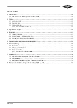
Page 19: ...3 4 2 Shut off valves welding connections 24 4 3 Connections and dimensional drawings 25 5 Line start permanent magnet motor LSPM 29 6 Commissioning 30 6 1 Evacuation 30 6 2 Charging with refrigerant...

Page 20: ...rvice life of the compressor 1 1 Also observe the following technical documents Operating Instructions KB 104 BITZER ECOLINE and ECOLINE VARISPEED Technical Information KT 230 compressor module for BI...

Page 21: ...arger systems installation of an additional cooling unit to limit the pressure by back condens ation Maximum allowable pressures standstill 2MME 07K 6PME 40K Low pressure side 100 bar High pressure si...

Page 22: ...30 Hz to 75 Hz operation 4FME 7K 4DME 10K authorised for 25 Hz to 70 Hz operation 4TME 20K 4PME 25K authorised for 25 Hz to 70 Hz operation 6TME 35K 6PME 40K authorised for 25 Hz to 70 Hz operation 2...

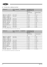
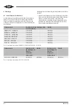
Page 23: ...free Select the vibration dampers according to the following tables Compressor Kit number article number 4 pieces Hardness 2MME 07K 2DME 7K 370 005 02 60 Shore 4FME 7K 4DME 10K 370 005 02 60 Shore 4T...

Page 24: ...315 53 di 22 3 da 30 4TSL 20K 4NSL 30K 361 315 54 di 28 7 da 35 Tab 4 Shut off valves and connection sizes high pressure side Compressor Art no shut off valve Designation Specifications refer to valv...

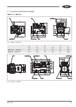
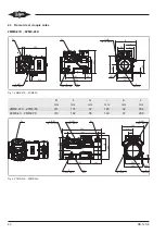
Page 25: ...L 192 99 J F B 293 86 453 343 320 K 212 G Fig 1 2MME 07K 2DME 7K B mm F mm G mm J mm K mm L mm 2MME 07K 2FME 5K 311 174 37 145 32 264 2EME 4K 2DME 7K 319 182 58 149 37 268 1 4 18 NPTF 5 12 10 M10x1 5...

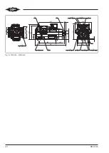
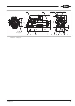
Page 26: ...PTF 2 HP M20x1 5 1 4 18 NPTF 1 HP M10x1 5 6 1 4 18 NPTF 5 12 10 1 2 14 NPTF 9 438 DL SL 3 LP 1 8 27 NPTF 21 21 280 330 414 75 222 807 450 44 681 145 374 413 80 11 7 16 20 UNF 12 7 16 20 UNF 16 155 Fig...

Page 27: ...HP 1 8 27 NPTF 10 11 SL DL 3 LP 1 8 27 NPTF Fig 4 2NSL 05K 2FSL 4K A mm D1 mm F mm J mm 2NSL 05K 2HSL 3K 343 65 148 247 2GSL 3K 2FSL 4K 373 95 148 277 198 241 90 121 261 123 263 424 223 111 268 334 6...

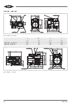
Page 28: ...mm J mm K mm L mm 4FSL 7K 4ESL 9K 464 101 247 387 37 306 4DSL 10K 464 101 247 387 42 310 4CSL 12K 497 134 280 420 42 310 173 385 G 367 170 142 H K 6 M x1 5 10 10 12 1 2 14 NPTF 21 619 304 300 256 19 1...

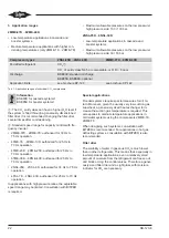
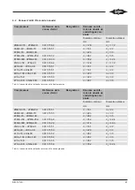
Page 29: ...e SL Suction gas line DL Discharge gas line Tab 6 Connection points Dimensions if specified may have tolerances accord ing to EN ISO 13920 B 5 Line start permanent magnet motor LSPM The compressors of...

Page 30: ...the system during the whole commis sioning process 6 1 Evacuation Switch on the oil heater Information For applications with CO2 the standing va cuum should reach a value of 0 67 mbar 500 microns befo...

Page 31: ...noid valves of the evaporator are closed de energised 6 3 Compressor start NOTICE Avoid strong pressure reduction in the crank case during the compressor start and during op eration Oil foam formation...

Page 32: ...ll below 30 C and pressure gas temperature not below 50 C Maximum discharge gas temperature measured at the discharge gas pipeline 10 cm distance from the discharge gas connection of the compressor 2M...

Page 33: ...and forms dry ice Danger of cold burns and frost bites Avoid uncontrolled deflating of CO2 When filling the system with CO2 wear gloves and goggles If uncontrolled CO2 emissions occur take the follow...

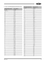
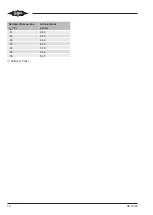
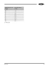
Page 34: ...87 8 42 78 7 41 70 6 40 67 5 39 65 4 38 64 3 37 66 2 36 69 1 35 74 0 34 81 1 33 90 2 33 00 3 32 12 4 31 26 5 30 42 6 29 59 Saturated vapour tem perature tsat C Absolute pressure p bar 7 28 78 8 27 99...

Page 35: ...KB 120 8 35 Saturated vapour tem perature tsat C Absolute pressure p bar 48 7 40 49 7 11 50 6 83 51 6 55 52 6 29 53 6 03 54 5 78 55 5 54 56 5 31 Critical point...

Page 36: ...nnes d arr t Raccords souder 41 4 3 Raccords et croquis cot s 42 5 Moteur aimant permanent d marrage direct LSPM 46 6 Mise en service 47 6 1 Mise sous vide 47 6 2 Remplir de fluide frigorig ne 47 6 3...

Page 37: ...t de l installation frigorifique durant toute la dur e de vie du compres seur 1 1 Tenir galement compte de la documentation technique suivante Instructions de service KB 104 BITZER ECOLINE et ECOLINE...

Page 38: ...r doivent tre isol s afin d vi ter que la temp rature ne passe en dessous du point de ros e Si n cessaire prendre d autres mesures pour limiter la pression comme par ex utilisation d un r servoir d ga...

Page 39: ...20K 4PME 25K autoris pour une plage de fr quences allant de 25 70 Hz 6TME 35K 6PME 40K autoris pour une plage de fr quences allant de 25 70 Hz 2NSL 05K 2CSL 6K autoris pour une plage de fr quences al...

Page 40: ...on et de refoulement S lection des amortisseurs de vibra tions l aide des tableaux suivants Compresseur Num ro de kit de montage r f rence 4 pi ces Duret 2MME 07K 2DME 7K 370 005 02 60 Shore 4FME 7K 4...

Page 41: ...53 di 22 3 da 30 4TSL 20K 4NSL 30K 361 315 54 di 28 7 da 35 Tab 4 Vannes d arr t et tailles de raccords c t haute pression Compresseur R f rence de la vanne d arr t D signation Donn es se r f rant la...

Page 42: ...2 99 J F B 293 86 453 343 320 K 212 G Fig 1 2MME 07K 2DME 7K B mm F mm G mm J mm K mm L mm 2MME 07K 2FME 5K 311 174 37 145 32 264 2EME 4K 2DME 7K 319 182 58 149 37 268 1 4 18 NPTF 5 12 10 M10x1 5 6 1...

Page 43: ...PTF 2 HP M20x1 5 1 4 18 NPTF 1 HP M10x1 5 6 1 4 18 NPTF 5 12 10 1 2 14 NPTF 9 438 DL SL 3 LP 1 8 27 NPTF 21 21 280 330 414 75 222 807 450 44 681 145 374 413 80 11 7 16 20 UNF 12 7 16 20 UNF 16 155 Fig...

Page 44: ...HP 1 8 27 NPTF 10 11 SL DL 3 LP 1 8 27 NPTF Fig 4 2NSL 05K 2FSL 4K A mm D1 mm F mm J mm 2NSL 05K 2HSL 3K 343 65 148 247 2GSL 3K 2FSL 4K 373 95 148 277 198 241 90 121 261 123 263 424 223 111 268 334 6...

Page 45: ...mm J mm K mm L mm 4FSL 7K 4ESL 9K 464 101 247 387 37 306 4DSL 10K 464 101 247 387 42 310 4CSL 12K 497 134 280 420 42 310 173 385 G 367 170 142 H K 6 M x1 5 10 10 12 1 2 14 NPTF 21 619 304 300 256 19 1...

Page 46: ...aspiration DL Conduite du gaz de refoulement Tab 6 Positions de raccordement Les cotes indiqu es sont susceptibles de pr senter une tol rance selon la norme EN ISO 13920 B 5 Moteur aimant permanent d...

Page 47: ...frigori g ne dans l huile des hautes pressions et le cas ch ant des fortes variations de pression apr s le processus de d marrage une sur charge et un manque de lubrification sont sus ceptibles d app...

Page 48: ...d env 10 bar En cas de refroidissement important de la bouteille de fluide frigorig ne il faut la r chauf fer au bain marie temp rature de l eau 40 C max Fermer les vannes d aspiration et les vannes d...

Page 49: ...gaz d aspiration faible En mati re de conditions de lubrification il faut satis faire aux exigences suivantes En r gle g n rale mettre le r chauffeur d huile en service en particulier durant les phase...

Page 50: ...x de machines ferm s Respecter les exigences de s curit sp cifi es par la norme EN 378 DANGER Le CO2 liquide s vapore tr s rapidement refroi dit durant le processus et forme de la glace s che Risque d...

Page 51: ...43 87 8 42 78 7 41 70 6 40 67 5 39 65 4 38 64 3 37 66 2 36 69 1 35 74 0 34 81 1 33 90 2 33 00 3 32 12 4 31 26 5 30 42 6 29 59 Temp rature de vapeur satur e tsat C Pression absolue p bar 7 28 78 8 27...

Page 52: ...KB 120 8 52 Temp rature de vapeur satur e tsat C Pression absolue p bar 48 7 40 49 7 11 50 6 83 51 6 55 52 6 29 53 6 03 54 5 78 55 5 54 56 5 31 Point critique...

Page 53: ...Notes...

Page 54: ...Notes...

Page 55: ...Notes...

Page 56: ...ermany Tel 49 7031 932 0 Fax 49 7031 932 147 bitzer bitzer de www bitzer de nderungen vorbehalten nderungen vorbehalten Subject to change Toutes modifications r serv es80411004 07 2019 80411004 07 201...

Reviews: