8
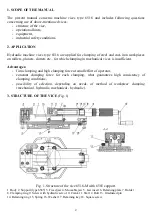
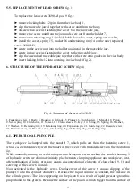
the plunger, the clamping force becomes multiplied in relation to the force resulting from crank
action. The piston 8 pushes the mandrel 7 and causes clamping of the workpiece.
6.2. OPERATIONAL HINTS
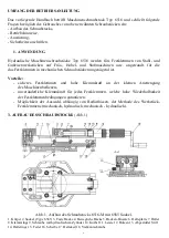
Screws 3690-M2, M3, M4 are fitted with external sleeve clutch, which enables initial selection
of working mode.
-
Clamping with hydraulic servo
(basic working mode) is realised through sliding of the
sleeve 12 towards the screw 1 (on the drawing the left extreme position – disengagement
of the clutch), the screw housing 3 should be fully screwed out, and the clutch sleeve
tongue 12 should be positioned opposite to the housing notch.
Application
: clamping of typical steel and cast iron elements or materials of similar resistance.
-
Mechanical – hydraulic clamping
We clamp initially the workpiece mechanically (the hydraulic system is disconnected i.e. the
clutch sleeve 12 is connected with housing 3, see mechanical clamping), and then we move the
sleeve left to unlock the hydraulic system and tighten as far as it goes with crank causing final
clamping of the workpiece and obtaining the mixed, i.e. mechanical – hydraulic clamping.
Application: when required is exceptionally high clamping force or elimination, prior to
activation of hydraulic servo, of bigger play between clamping appliance and workpiece.
-
Mechanical clamping
Screw out the screw housing as far as it goes and connect the clutch sleeve 12 with housing 3.
This causes locking of hydraulic system, thus the clamping is realised in the same way as with
help of conventional lead screw. Application: clamping of workpieces made of materials liable
to deformation, which surface could be damaged, when clamped with hydraulic servo, e.g.
aluminium, plastic and thin-walled details.
7. MAINTENANCE OF THE SCREW
7.1. PERIODICAL MAINTENANCE OF CLUTCH SCREW
(pos. 6 fig. 4).
To assure long life of the internal clutch screw 6, we recommend to replenish every six months,
or, in the case of intense use (more than 1000 clamping cycles daily) every month, the grease
for moveable connections containing molybdenum disulfide MoS
2
or LOCTITE 8103 grease.
For this purpose:
► put out the spring pin 20 connecting the housing 3 with clutch screw 6,
► slide the housing 3 from the body 2,
► replenish the grease on threaded surface of the clutch screw,
► check the condition of the sealing ring pos. 27, replace, if necessary,
► oil the internal surface of the housing 3 with machine oil,
► assemble the screw, sliding carefully the housing as far as it goes so that not to
damage the sealing ring and hammer the spring pin 20 into the opening connecting the
housing with the screw.

