1. Read this Manual thoroughly before installation and operation.
Do not
proceed with installation and
operation if you have any questions or do not understand anything in this Manual. Contact your local
Distributor, or BIRO first.
3
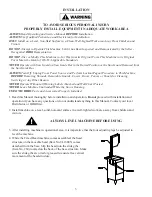
3. After installing machine in operational area, it is imperative that the four adjusting legs be adjusted to
level the machine.
ALWAYS LEVEL MACHINE BEFORE USING
USE ONLY
BIRO
Parts and Accessories Properly Installed.
ALWAYS
Read Operating and Service Manual
BEFORE
Installation.
ALWAYS
Use Qualified Technician and Electrician for Installation.
ONLY
Install on a Level, Non-Skid Surface in a Clean, Well-Lighted Work area Away From Children and
Visitors.
NEVER
Operate Without all Warning Labels Attached and Wall Chart Posted.
DO NOT
Attempt to Operate This Machine Until it has Been Inspected and Demonstrated by the Seller -
Recognized
BIRO
Representative
.
DO NOT
Alter or Modify This Machine in Any Way from its Original Form. This Machine in its Original
Form Meets the Intent of O.S.H.A Applicable Standards.
TO AVOID SERIOUS PERSONAL INJURY
PROPERLY INSTALL EQUIPMENT IN ADEQUATE WORK AREA
ALWAYS
Turn Off, Unplug From Power Source and Perform Lockout/Tagout Procedure to This Machine
BEFORE
Removing Shrouds, Removable Guards, Covers, Doors, Fences or Panels for Cleaning,
Servicing or Any Other Reason.
NEVER
Leave Machine Unattended While the Saw is Running.
2. Install machine on a level, solid, non-skid surface in a well-lighted work area away from children and
visitors.
NEVER
Operate with Saw Guard on Saw Guide Bar in the Raised Position or the Saw Guard Removed from
the Saw Guide Bar.
4. While the Fixed Head machine comes assembled, the head
structure on the movable head (Item No.TL16005) comes
detached from the base. Slip the head into the slide gibs
(Item No. 260) located on the back of the base structure. Make
sure the slide gibs are oiled or greased to ensure free vertical
movement of the head structure.
INSTALLATION
Summary of Contents for 3334SS-4003FH-TL
Page 2: ......
Page 12: ...9 OPERATOR S NOTES ...
Page 24: ...21 COMMON TRUE LEFT PARTS ...
Page 25: ...22 COMMON TRUE LEFT PARTS ...
Page 32: ...29 ...
Page 33: ...30 ...


