background image

Index

46

H

Home Monitoring


 . . . . . . . . . . . . . . . . . . . . . 3

Hospital


. . . . . . . . . . . . . . . . . . . . . . . . . . . . 30

I

Illumination


. . . . . . . . . . . . . . . . . . . . . . . . . 24

L

Landline connection


. . . . . . . . . . . . . . . . . . . 4

Light 1


. . . . . . . . . . . . . . . . . . . . 18

21

22

24

Light 2


. . . . . . . . . . . . . . . . . . . . . . . . . . 18

24

M

Maintenance


. . . . . . . . . . . . . . . . . . . . . . . . 28

O

Operate


 . . . . . . . . . . . . . . . . . . . . . . . . . . . . 21

Operating light


 . . . . . . . . . . . . . . . . 18

21

24

Original parts


 . . . . . . . . . . . . . . . . . . . . . 5

37

Outlet


. . . . . . . . . . . . . . . . . . . . . . . . . . . . . . 17

P

Package Contents


 . . . . . . . . . . . . . . . . . . . . 5

Perform call back


 . . . . . . . . . . . . . . . . . . . 22

Phone inlet 1


 . . . . . . . . . . . . . . . . . . . . . 9

13

Phone inlet 2


 . . . . . . . . . . . . . . . . . . . . . . . 10

Physician call back light


 . . . . . . . . . . . . . . 24

Physician's phone number


 . . . . . . . . . 20

22

Port for power connection


 . . . . . . . . . . . . 16

Power connection port


 . . . . . . . . . . . . . . . 16

Power supply unit


 . . . . . . . . . . . . . . 5

16

38

Precautionary measures


. . . . . . . . . . . . . . 30

R

Ready-for-service status


 . . . . . . . . . . . . . 21

Recommended separation distances


 . . . 44

Repair


. . . . . . . . . . . . . . . . . . . . . . . . . . . . . 31

CM-S_TLine.book  Page 46  Wednesday, December 21, 2011  4:58 PM

Summary of Contents for CardioMessenger-S TLine

Page 1: ...CardioMessenger S TLine Transmitter for BIOTRONIK Home Monitoring Technical Manual 371017 B_GA_CardioMessenger S_TLine_en US_Cover indd 1 20 12 2011 19 08 25 ...

Page 2: ...llow green page 21 Use only original power supply units page 16 Slot for the brief instructions guide page 20 Connection for the power supply page 16 Connections for the landline page 8 15 U2 371017 B_GA_CardioMessenger S_TLine_en US_Cover indd 2 20 12 2011 19 08 26 ...

Page 3: ...dline 8 Connection to the power supply 16 Self test 18 Insert brief instructions guide 20 Operate 21 Check lights 21 Call back function 22 Switching off the system 23 Debugging 24 Cleaning maintenance and disposal 28 Precautionary measures 30 Guidelines 33 Technical data 37 Appendix 39 Index 45 371017 B CM S_TLine book Page 1 Wednesday December 21 2011 4 58 PM ...

Page 4: ...2 CM S_TLine book Page 2 Wednesday December 21 2011 4 58 PM ...

Page 5: ...n a daily basis while you are at home Your cardioligist or physician can catch up at regular intervals on how your heart is doing How Home Monitoring works Your device is equipped with a special transmitter 1 Usually at night the transmitter sends daily information on your heart to the patient device your CardioMessenger 2 The transmission power from your implanted device is low and does not impai...

Page 6: ...ailable on a protected web site Your cardiologist 5 or the physician who usually carries out the follow up examinations has access to this web site Based on the information received your cardiologist or physician can decide if your device is best configured or if the therapy needs adjustments In this way Home Monitoring serves as a practical diagnostic aid to your physician CM S_TLine book Page 4 ...

Page 7: ...e using them Use only components which are undamaged The delivery includes the following Transport packaging Keep the transport packaging and use it if you return the CardioMessenger to your physician CardioMessenger S TLine Power supply unit with electricity cable and DC plug Telephone cable CM S_TLine book Page 5 Wednesday December 21 2011 4 58 PM ...

Page 8: ...an Warning Use only the original parts included for details see Technical data page 37 Other equipment may impair proper functioning of the CardioMessenger and increase the emitted interference and the CardioMessenge s susceptibility to interference The label on the back side of the CardioMessenger indicates the approved power supply CM S_TLine book Page 6 Wednesday December 21 2011 4 58 PM ...

Page 9: ... the lights disturb you in your sleep turn the CardioMessenger away from you Do not place the CardioMessenger on the floor next to or under your bed 2 Do not place the CardioMessenger next to a television set microwave oven or a similar source of electromagnetic interference 2 Do not expose the CardioMessenger to temperatures exceeding 40 C 104 F Do not put it on a place with direct sun light and ...

Page 10: ...usual Note The CardioMessenger is designed to operate with standard analog phone lines providing Plain Old Telephone Service POTS Compatibility with other phone lines or services e g Voice over IP VoIP via analog or digital lines cable TV phone lines or ISDN is not guaranteed In these cases compatibility testing at the patient s home is recommended Proper set up of the system at the patient s home...

Page 11: ... CardioMessenger and telephone together in one telephone wall jack proceed as follows 1 On the back side of the CardioMessenger Remove the sealing plug from phone inlet 1 Phone inlet 1 is labeled with the following symbol 2 Unplug the telephone cable from the telephone wall jack CM S_TLine book Page 9 Wednesday December 21 2011 4 58 PM ...

Page 12: ... cable to phone inlet 1 of the CardioMessenger The telephone is now connected to the CardioMessenger 4 Remove the sealing plug from phone inlet 2 Phone inlet 2 is labeled with the following symbol CM S_TLine book Page 10 Wednesday December 21 2011 4 58 PM ...

Page 13: ...connect one end to phone inlet 2 6 Connect the other end of the supplied telephone cable to the telephone wall jack 7 Check the telephone connection Lift and listen to the receiver The usual dialing tone should be audible CM S_TLine book Page 11 Wednesday December 21 2011 4 58 PM ...

Page 14: ...phone and CardioMessenger are now connected to the landline As a next step connect the CardioMessenger to the power supply see Connection to the power supply page 16 CM S_TLine book Page 12 Wednesday December 21 2011 4 58 PM ...

Page 15: ... operate the CardioMessenger in a telephone wall jack to which no other devices are connected proceed as follows 1 On the back side of the CardioMessenger Remove the sealing plug from phone inlet 1 Phone inlet 1 is labeled with the following symbol CM S_TLine book Page 13 Wednesday December 21 2011 4 58 PM ...

Page 16: ... 2 Take the supplied telephone cable and connect one end to phone inlet 1 3 Connect the other end of the supplied telephone cable to the telephone wall jack CM S_TLine book Page 14 Wednesday December 21 2011 4 58 PM ...

Page 17: ...nection 15 The CardioMessenger is now connected to the landline As a next step connect the CardioMessenger to the power supply see Connection to the power supply page 16 CM S_TLine book Page 15 Wednesday December 21 2011 4 58 PM ...

Page 18: ...ata page 37 Other equipment may impair proper functioning of the CardioMessenger and increase the emitted interference and the CardioMessenger s susceptibility to interference The label on the back side of the CardioMessenger indicates the approved power supply 1 Connect the DC plug at the end of the electricity cable to the port on the left side of the CardioMessenger The connector port is labele...

Page 19: ... 17 2 Connect the power supply unit to the outlet See that the outlet is not controlled by a light switch This will prevent you from turning off the CardioMessenger accidentally CM S_TLine book Page 17 Wednesday December 21 2011 4 58 PM ...

Page 20: ...uminates yellow The connection check can take up to 15 minutes As soon as the connection has been checked successfully the operating light illuminates green The CardioMessenger is now ready for use The CardioMessenger is intended for continuous operation It should be connected at all times especially at night Note It is a sign of malfunction if the operating light remains illuminated yellow for mo...

Page 21: ... using one telephone wall jack variant A the readily connected CardioMessenger looks as follows If you are operating the CardioMessenger on a free telephone wall jack variant B the readily connected CardioMessenger looks as follows CM S_TLine book Page 19 Wednesday December 21 2011 4 58 PM ...

Page 22: ...me and phone number of your cardiologist or of the physician who usually carries out follow up examinations on the back cover of this guide 3 Insert the brief instructions guide into the slot on the left side into the housing of the CardioMessenger Now the brief instructions guide with your cardiologist s or physician s phone number are ready at hand Use it if the call back function of the CardioM...

Page 23: ...Service Center Note It indicates a malfunction if the operating light illuminates yellow or does not light up at all For details on the subject of Debugging see page 24 Check lights Check once a day whether either of the two lights is illuminated Usually the operating light illuminates green The call back light is not illuminated Note The functions of your device are not affected at any time by th...

Page 24: ...usually carries out the follow up examinations will let you know whether he or she intends to use this function in general Perform call back Call your cardiologist or the physician who usually carries out the follow up examinations as soon as you realize that the call back light is blinking Note The brief instructions guide with your cardiologist s or physician s phone number is located in the hou...

Page 25: ... CardioMessenger performs the self test Afterwards the operating light will illuminate green and the call back light will no longer be blinking Note For details on the subject of Connection to the power supply see page 16 Switching off the system The CardioMessenger does not have an on off switch To turn off the CardioMessenger disconnect it from the main supply 1 Remove the power plug from the wa...

Page 26: ...Yellow blinking both lights blink yellow Error type B Repeat the self test see next page for further details Operating light Off Error type A Check the power supply see next page Green illumination The CardioMessenger is ready for use no malfunction Yellow blinking both lights blink yellow Error type B Repeat the self test see next page for further details Yellow illumination only this light illum...

Page 27: ... cardiologist or the physician who usually carries out the follow up examinations Error type B Repeat the self test Both lights blink yellow The CardioMessenger has not concluded the self test It is not yet ready for use 1 Remove the power supply unit from the wall outlet 2 Reconnect it The CardioMessenger restarts and performs the self test Both lights will illuminate yellow The call back light w...

Page 28: ...t connect to the BIOTRONIK Service Center 1 Make sure that the one end of the telephone cable is properly inserted into the telephone wall jack 2 Make sure that the other end of the tele phone cable is properly inserted into phone inlet 1 on the back of the CardioMessenger 3 Check whether the telephone line is available by connecting your telephone to the CardioMessenger Lift the receiver and list...

Page 29: ...ain Old Telephone Service POTS Compatibility with other phone lines or services e g Voice over IP VoIP via analog or digital lines cable TV phone lines or ISDN is not guaranteed In these cases compatibility testing at the patient s home is recommended Proper set up of the system at the patient s home may require installation of adapters and or analog phone lines Please contact your telephone servi...

Page 30: ... cloth 2 For cleaning you must only use a lightly water damped cloth Do not bring the CardioMessenger into direct contact with water or solvents Maintenance The CardioMessenger is intended for continuous automatic operation Once correctly installed ongoing actions by you are typically not required e g no maintenance is required In continuous operation the longevity of the contained button cell cor...

Page 31: ...in accordance with environmental protection regulations If no longer required or if defective please return the CardioMessenger and all other supplied parts to the physician Your physician will return all parts to BIOTRONIK BIOTRONIK ensures the disposal in accordance with the national design of the European guideline 2002 96 EC on electric and electronic used devices WEE CM S_TLine book Page 29 W...

Page 32: ...pply for electrical devices in hospitals and do not apply when the CardioMessenger is used at home Warning Use the CardioMessenger only if it is undamaged Return a damaged CardioMessenger to your physician Warning Use only the original parts included for details see Technical data page 37 Other equipment may impair proper functioning of the CardioMessenger and increase the emitted interference and...

Page 33: ...r Caution Protect the CardioMessenger from Water and high humidity Temperatures above 40 C 104 F for example from direct sunlight and strong halogen spotlights Temperatures below 10 C 50 F Solvents acids detergents and lyes Caution The CardioMessenger may only be opened and repaired by authorized trained personnel CM S_TLine book Page 31 Wednesday December 21 2011 4 58 PM ...

Page 34: ...Precautionary measures 32 CM S_TLine book Page 32 Wednesday December 21 2011 4 58 PM ...

Page 35: ...ation This device complies with Part 15 of the FCC Rules Operation is subject to the following two conditions 1 this device may not cause harmful interference and 2 this device must accept any interference received including interference that may cause undesired operation This transceiver shall be used only in accordance with the FCC rules governing the Medical Implant Communications Service Analo...

Page 36: ...ate radio frequency energy and if not installed and used in accordance with the instructions may cause harmful interference to radio communications However there is no guarantee that interference will not occur in a particular installation If this equipment does cause harmful interference to radio or television reception which can be determined by turning the equipment off and on the user is encou...

Page 37: ...the following number IC 125A 0015 The term IC before the certification registration number only signifies that the Industry Canada technical specifications were met This device may not interfere with stations operating in the 400 150 406 000 MHz band in the meteorological aids meteorological satellite and earth exploration satellite services and must accept any interference received including inte...

Page 38: ... 1 2 in every respect Warning Other equipment including portable and mobile RF radiocommunications equipment may interfere with the CardioMessenger even if this equipment complies with CISPR emission requirements However this possible interference does not affect the device functionality Warranty The CardioMessenger and all original components by BIOTRONIK are not subject to warranty when used imp...

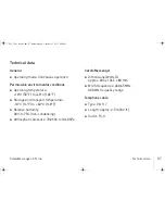
Page 39: ...torage and transport temperature 10 C 14 F to 60 C 140 F 2 Relative humidity 30 to 75 non condensing 2 Atmospheric pressure 700 hPa to 1060 hPa CardioMessenger 2 Dimensions WxHxD approx 203 x 136 5 x 80 mm 2 MICS frequencies 403 65 MHz 300 kHz frequency range Telephone cable 2 Type VK 117 2 Length approx 2 5 m 8 2 ft 2 Outlet Rj 11 CM S_TLine book Page 37 Wednesday December 21 2011 4 58 PM ...

Page 40: ...tage 5 V DC 5 2 4 A 12 W 2 Safety class II or 2 Type Nordic Power SAC SA110D 05 2 Dimensions WxHxD approx 69 x 45 x 35 mm 2 DC plug output Outer diameter 5 5 mm mass Inner diameter 2 1 mm plus 2 Input voltage 100 240 V 50 60 Hz 300 mA 2 Output voltage 5 1 V DC 5 2 A 10 2 W 2 Safety class II Technical manual 2 Technical manual with brief instructions guide CardioMessenger S TLine CM S_TLine book Pa...

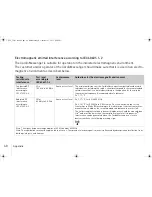
Page 41: ...p 1 The CardioMessenger uses RF energy only for its internal function Therefore the HF interference is very low and not likely to cause any interference in nearby electronic equip ment High frequency interference according to CISPR 11 Class B The CardioMessenger is suitable for use in all areas including living space and those areas that are directly connected to a public power supply system that ...

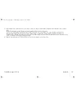
Page 42: ...he suitable transmission frequency Recommended safe distance D 1 17 Radiated RF interference according to IEC 61000 4 3 3V m 80 MHz to 2 5 GHz Same as test level D 1 17 for 80 to 800 MHz D 2 34 for 800 MHz to 2 5 GHz with P as the nominal output of the transmitter in Watts W according to the information from the transmitter manufacturer and d as the recommended safe distance in meters m The field ...

Page 43: ...ers an electromagnetic site survey should be considered If the measured field strength in the location in which the CardioMessenger is used exceeds the applicable RF compliance level above the CardioMessenger should be observed to verify normal operation If abnormal performance is observed additional measures may be necessary such as re orienting or relocating the CardioMessenger b Above the frequ...

Page 44: ... discharge 8 kV air discharge Same as test level Floors should be made of wood or cement or have ceramic tiles When the floor consists of a synthetic material the relative humidity must be at least 30 Rapid transient electrical disturbances bursts According to IEC 61000 4 4 2 kV for power supply lines 1 kV for input output lines Same as the test level The quality of the supply voltage should corre...

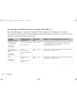
Page 45: ...o that in a typical business and or hospital Magnetic field at the supply frequencies 50 60 Hz According to IEC 61000 4 8 3A m Same as the test level The magnetic field strength should correspond to the typical value in business and hospital environments Comment UT is the mains alternating voltage before applying the test levels Checking immunity to noise Test level according to IEC 60601 1 2 Conf...

Page 46: ... 4 100 11 7 11 7 23 4 For transmitters whose maximum nominal output is not indicated in the above table the distance can be calculated using the equation in the column where P is the maximum nominal output of the transmitter in Watts W according to the transmitter s manufacturer Note The higher frequency range applies at 80MHz and at 800MHz Note These guidelines may not be applicable in all cases ...

Page 47: ...heck the telephone connection 11 Checking the power supply 25 Clean it 28 Cleaning 28 Connection to the landline 8 19 Connection to the power supply 16 19 D Damaged CardioMessenger 6 30 DC plug 5 23 38 Debugging 24 Defective CardioMessenger 30 Device 3 7 Disposal 29 Distance to the device 7 E Electricity cable 5 16 23 Electromagnetic Compatibility 36 Electromagnetic emitted interference 39 G Green...

Page 48: ...37 Outlet 17 P Package Contents 5 Perform call back 22 Phone inlet 1 9 13 Phone inlet 2 10 Physician call back light 24 Physician s phone number 20 22 Port for power connection 16 Power connection port 16 Power supply unit 5 16 38 Precautionary measures 30 R Ready for service status 21 Recommended separation distances 44 Repair 31 CM S_TLine book Page 46 Wednesday December 21 2011 4 58 PM ...

Page 49: ...7 Switch off the system 23 Switching on the system 21 23 T Technical data 37 Telephone cable 5 10 11 14 37 Telephone wall jack 8 9 11 13 14 Transmitter of the device 3 7 Turn off the call back light 23 U Unsuitable installation location 7 W Warranty 36 Y Yellow light 18 22 24 CM S_TLine book Page 47 Wednesday December 21 2011 4 58 PM ...

Page 50: ...CM S_TLine book Page 48 Wednesday December 21 2011 4 58 PM ...

Page 51: ...371017 B_GA_CardioMessenger S_TLine_en US_Cover indd 3 20 12 2011 19 08 26 ...

Page 52: ...TRONIK SE Co KG BIOTRONIK SE Co KG Woermannkehre 1 12359 Berlin Germany Tel 49 0 30 68905 0 Fax 49 0 30 6852804 BIOTRONIK Inc 6024 SW Jean rd Bldg B Lake Oswego OR 97035 Phone 800 547 0394 24 hr Fax 503 635 9936 sales biotronik com www biotronik com 12 D xx Revision B 2012 01 11 371017 B_GA_CardioMessenger S_TLine_en US_Cover indd 4 20 12 2011 19 08 26 ...

Reviews: