background image

iDEQ-T1 Setup Manual 

36 

Software 

Installing Software 

1.  Insert the Setup DVD to the optical drive. The driver installation program would 

appear if the Auto-run function has been enabled. 

2. Select 

Software Installation

, and then click on the respective software title. 

3.  Follow the on-screen instructions to complete the installation. 

Launching Software 

After the installation process is completed, you will see the software icon showing on 

the desktop. Double-click the icon to launch it. 

Note1: 

All the information and content about following software are subject to be changed without 

notice. For better performance, the software is being continuously updated.   

Note2:

 The information and pictures described below are for your reference only. The actual 

information and settings on board may be slightly different from this manual. 

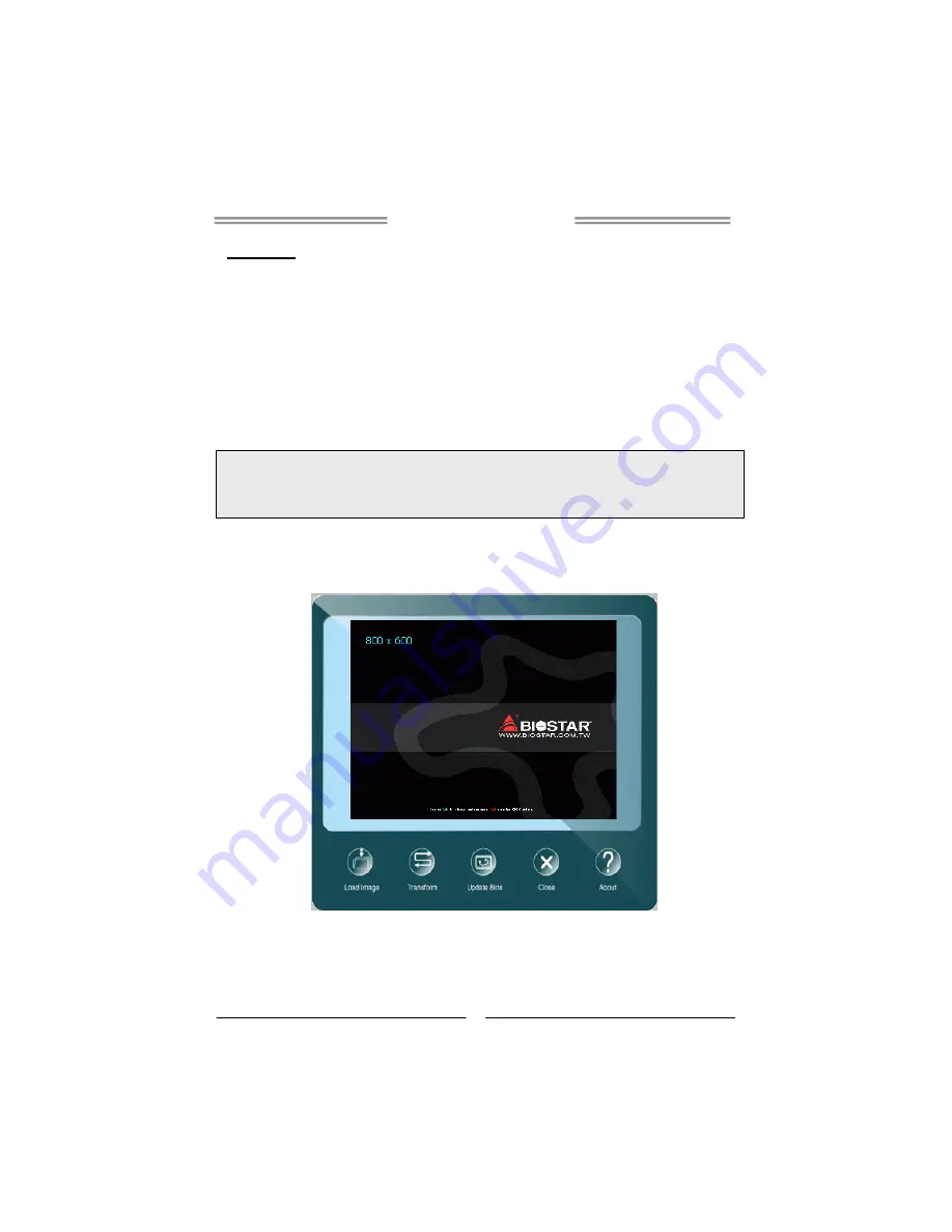
BIOScreen Utility 

This utility allows you to personalize your boot logo easily. You can choose BMP as 
your boot logo so as to customize your computer. 


Please follow the step-by-step instructions below to update boot logo: 

 Load Image

Choose the picture as the boot logo. 

 Transform

Transform the picture for BIOS and preview the result. 

 Update Bios

Write the picture to BIOS Memory to complete the update. 

Summary of Contents for iDEQ-T1 IJ1800T1

Page 1: ...e will not occur in a particular installation The vendor makes no representations or warranties with respect to the contents here and specially disclaims any implied warranties of merchantability or f...

Page 2: ...Installing a 2 5 inch HDD 6 VESA Bracket Optional 7 Antenna Optional 8 Chapter 3 BIOS Setup 9 Main Menu 11 Advanced Menu 12 Chipset Menu 22 Security Menu 26 Performance Menu 28 Boot Menu 30 Exit Menu...

Page 3: ...and cold Keep liquids away from the mini PC and keyboard Never wipe the interior of the system with water or dip the system in water Before connecting to any peripheral please turn off the power of t...

Page 4: ...separately 1x Mini PCIe Connector Audio Realtek Codec ALC662 Support 2x Port with Line out MIC in Storage 1x SATA II connector data transfer rates up to 3 0Gb s Rear I O DC jack 19V DC in 1x USB 3 0...

Page 5: ...iDEQ T1 Setup Manual 3 Getting to Know Your System Front Panel Rear Panel...

Page 6: ...installation Disassembling the Cover 1 Loosen four screws on the bottom cover then turn the system over 2 Place the tip of your fingernail into the tiny gap between the cover and the chassis then pull...

Page 7: ...Module Insert WiFi module into mini PCIe slot and fasten screw Connect antenna line to MAIN on the WiFi module Note Wi Fi module sold separately B Installing Memory Module 1 35V 1 5V Insert memory mo...

Page 8: ...iDEQ T1 Setup Manual 6 C Installing a 2 5 inch HDD 1 Fasten HDD bracket with HDD 2 Connect the SATA cable to the HDD and system board 3 Screw the HDD bracket back to the system...

Page 9: ...tional 1 The mounting kit has either the VESA 75 mm or 100 mm mounting pattern 2 Secure the VESA mounting bracket to your monitor with four screws 3 Place your PC on VESA bracket and make sure the PC...

Page 10: ...iDEQ T1 Setup Manual 8 Antenna Fasten antenna to the connector Note After the system assembly please place the rubber stand to each screw hole...

Page 11: ...pset fine tuning options are also included in UEFI BIOS The rest of this manual will to guide you through the options and settings in UEFI BIOS Setup Plug and Play Support This AMI UEFI BIOS supports...

Page 12: ...sure optimum performance of the motherboard If the system becomes unstable after changing any settings please load the default settings to ensure system s compatibility and stability Use Load Setup De...

Page 13: ...ion BIOS Information It shows system information including UEFI BIOS version Product Name Build Date and etc Total Memory Shows system memory size VGA shard memory will be excluded System Language Cho...

Page 14: ...PU Super I O Power Management and other system devices Notice Beware of that setting inappropriate values in items of this menu may cause system to malfunction ACPI Settings Enable ACPI Auto Configura...

Page 15: ...ions Power Off Default Power On Last State EuP Control When EuP is enabled the system will meet EuP requirement Options Disabled Default Enabled PME Wake up from S5 The item enables the system to wake...

Page 16: ...iDEQ T1 Setup Manual 14 SMART FAN Control System Smart Fan2 This item allows you to control the System Smart Fan function Options Auto Default Full Running IT8627E H W Monitor...

Page 17: ...abled Default Enabled Note The following items appear only when you set the ISCT Support function to Enabled ISCT Notification Control Options Enabled Default CPU Configuration This item shows CPU Inf...

Page 18: ...he L2 prefetching of adjacent cache lines Options Enabled Default Disabled Intel Virtualization Technology When enabled a VMM can utilize the additional hardware capabilities provided by Vanderpool Te...

Page 19: ...ons No Limit Default C0 C1 C3 C6 C7 SATA Configuration The BIOS will automatically detect the presence of SATA devices Serial ATA SATA This item enables disables Serial ATA Device Options Enabled Defa...

Page 20: ...twork Stack function to Enabled IPv4 PXE Support This item enables or disables IPv4 PXE Boot Support If disabled IPv4 booth option will not be created Options Enabled Default Disabled IPv6 PXE Support...

Page 21: ...es This item sets the display mode for option ROM Options Force BIOS Default Keep Current INT19 Trap Response BIOS reaction on INT19 trapping by Option ROM IMMEDIATE execute the trap right away POSTPO...

Page 22: ...mines OpROM execution policy for devices other than Network Storage or video Options UEFI first Default Legacy only USB Configuration Legacy USB Support The item allows you to enable Legacy USB suppor...

Page 23: ...or Control Bulk and Interrupt transfers Options 20 sec Default 1 sec 5 sec 10 sec Device reset time out The item sets USB mass storage device Start Unit command time out Options 20 sec Default 10 sec...

Page 24: ...ds nearing the speed of the CPU itself uses when communicating with its own special components Notice Beware of that setting inappropriate values in items of this menu may cause system to malfunction...

Page 25: ...used by the Internal Graphics Device Options 64M Default 96M 128M 160M 192M 224M 256M 288M 320M 352M 384M 416M 448M 480M 512M DVMT Total Gfx Mem This item selects DVMT5 0 Total Graphic Memory size use...

Page 26: ...e This item enables or disables mode of operation of xHCI controller Options Smart Auto Default Auto Enabled Disabled USB 2 0 EHCI Support This item controls the USB EHCI USB2 0 functions One EHCI con...

Page 27: ...s item sets PCI Express Active State Power Management settings Options Auto Default L0s L1 L0sL1 Disabled Speed This item selects PCI Express port speed Options Auto Default Gen1 Gen2 Onboard Lan This...

Page 28: ...or Password User Password This item sets User Password Secure Boot Menu Secure Boot Secure Boot flow control Secure Boot can be enabled only when 1 Platform Key PK is enrolled and Platform is operatin...

Page 29: ...KEK file from your system Set new KEK Allows you set new KEK file Append Var to KEK Allows you append Var to KEK Authorized Signature Database DB Delete DB Allows you to delete the DB file from your s...

Page 30: ...s and default settings might be different by RAM or CPU models DRAM Voltage This item sets DRAM Voltage Options Auto Default 1 35V 1 40V 1 45V 1 50V DRAM Timing Select This item sets DRAM Timing Selec...

Page 31: ...me Range 1 511 Options Auto Default Write to Read Delay tWTR This item allows you to select Internal Write to Read Command Delay Range 3 31 Options Auto Default Active to Active Delay tRRD This item a...

Page 32: ...able disable Full Screen Logo Show function Options Enabled Default Disabled BIOS Flash protection While enabled it can t flash write and flash erase by SMI Options Enabled Default Disabled Boot Succe...

Page 33: ...tem after saving the changes Restore Defaults This selection allows you to reload the BIOS when problem occurs during system booting sequence These configurations are factory settings optimized for th...

Page 34: ...Flasher BIOSTAR BIOS Flasher is a BIOS flashing utility providing you an easy and simple way to update your BIOS via USB pen drive Note1 This utility only allows storage device with FAT32 16 format a...

Page 35: ...shows up press DEL key to enter BIOS setup After entering the BIOS setup please go to the Save Exit using the Restore Defaults function to load Optimized Defaults and select Save Changes and Reset to...

Page 36: ...will be asked you to reboot the system Click OK to reboot 8 While the system boots up and the full screen logo shows up press DEL key to enter BIOS setup After entering the BIOS setup please go to th...

Page 37: ...e process is finished click on OK to reboot the system 7 While the system boots up and the full screen logo shows up press DEL key to enter BIOS setup After entering the BIOS setup please go to the Sa...

Page 38: ...nd content about following software are subject to be changed without notice For better performance the software is being continuously updated Note2 The information and pictures described below are fo...

Page 39: ...that you would like to send the copy to Provide the name of the power supply manufacturer and the model no Send the mail out Save these information to a txt file Exit this dialog Select your area or...

Page 40: ...mail Note1 We will not share customer s data with any other third parties so please feel free to provide your system information while using eHot Line service Note2 If you are not using Outlook Expres...

Page 41: ...ep 2 Click on start menu and input regedit in the search bar Press enter to open the registry editor Look for the following directory in the registry editor Computer HKEY_LOCAL_MACHINE SOFTWARE Intel...

Page 42: ...History along with other settings To launch the application select the application Intel Smart Connect Technology in the Start menu Windows 7 or Start screen Windows 8 8 1 to launch the configuration...

Page 43: ...m click on each software title to launch the installation program C Manual Aside from the paperback manual we also provide manual in the Driver DVD Click on the Manual icon to browse for available man...

Page 44: ...to disk controller board Make sure both ends are securely plugged in check the drive type in the standard CMOS setup 2 Backing up the hard drive is extremely important All hard disks are capable of br...

Page 45: ...on Processor J1800 1M Cache up to 2 58 GHz Intel DDR3L 1333 1 35 1 5 2x DDR3L SO DIMM 16 DIMM non ECC 512 1 2 4 8 DDR3L www biostar com tw LAN RTL8111G RJ 45 1 WLAN PCIe 1 Realtek ALC662 2 SATA II 1 3...

Page 46: ...cteur Audio Realtek Codec ALC662 Soutient 2x Port avec Line sortie MIC entr e Stockage 1x SATA II connecteur taux de transfert de donn es jusqu 3 0Gb s Arri re I O DC Jack 19V DC in 1x USB 3 0 Port 1x...

Page 47: ...r Audio Realtek Codec ALC662 Unterst tzung 2x Anschluss mit Line out MIC in Lager 1x SATA II Steckverbinder Daten bertragungsrate bis zu 3 0Gb s R ckseite I O DC Klinkenstecker 19V DC in 1x USB 3 0 An...

Page 48: ...e udio Realtek Codec ALC662 Suporta 2x Portas com Line out MIC in Armazenamento 1x conector SATA II transfer ncia de dados at 3 0Gb s I O Traseiro Porta DC 19V DC in 1x Porta USB 3 0 1x Porta USB 2 0...

Page 49: ...5V 2xDDR3L SO DIMM 16 DIMM ECC 512 1 2 4 8 DDR3L www biostar com tw LAN RTL8111G 1x Ethernet RJ 45 WLAN Wi Fi 1x PCIe Realtek Codec ALC662 2 x Line out MIC in 1x SATA II 3 0 I O DC 19V DC in 1x USB 3...

Page 50: ...35V 1 5V 2x DDR3L SO DIMM 16 GB DIMM non ECC 512MB 1 2 4 8 GB DDR3L www biostar com tw LAN RTL8111G 1x RJ 45 WLAN Wi Fi 1x Mini PCIe Realtek Codec ALC662 2x 1x SATA II 3 0Gb s I O DC 19V DC in 1x USB...

Page 51: ...Conector Audio Realtek Codec ALC662 Soportar 2x Puerto con L nea out MIC in Almacenaje 1x SATA II conector tarifa de transferir datos hasta 3 0Gb s I O Trasero DC gato 19V DC in 1x Puerto de USB 3 0 1...

Reviews: