14 |
Chapter 2: Hardware installation
2.7 Headers & Connectors
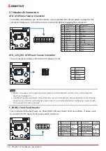
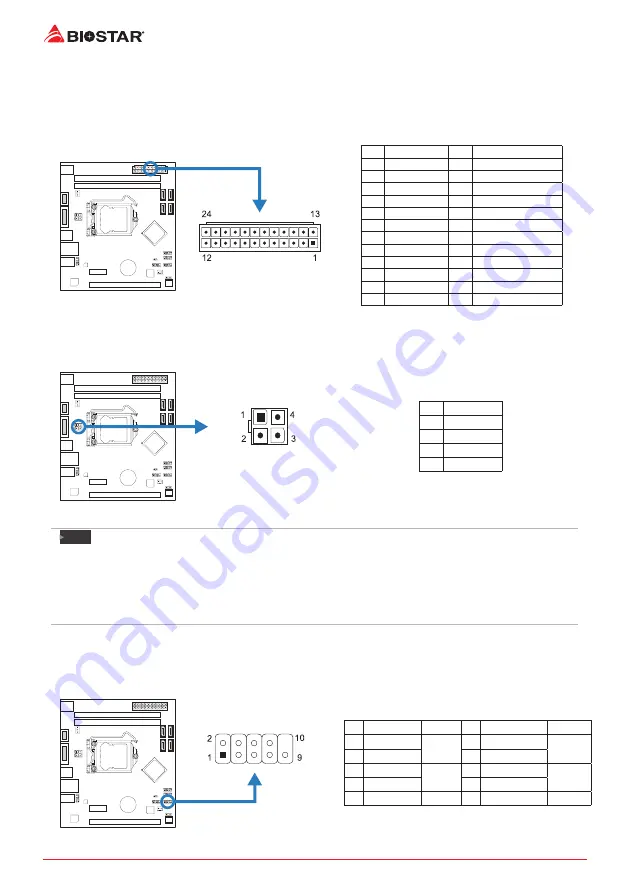
ATX: ATX Power Source Connector
For better compatibility, we recommend to use a standard ATX 24-pin power supply for this
connector. Make sure to find the correct orientation before plugging the connector.
Pin Assignment
Pin Assignment
13
+3.3V
1
+3.3V
14
-12V
2
+3.3V
15
Ground
3
Ground
16
PS_ON
4
+5V
17
Ground
5
Ground
18
Ground
6
+5V
19
Ground
7
Ground
20
NC
8
PW_OK
21
+5V
9
Standby 5V
22
+5V
10
+12V
23
+5V
11
+12V
24
Ground
12
+3.3V
ATX_12V_2X2: ATX Power Source Connector
The connector pr12V to the CPU power circuit.
Pin Assignment
1
+12V
2
+12V
3
Ground
4
Ground
Note
»
Before you power on the system, please make sure that both ATX and ATX_12V_2X2 connectors
have been plugged-in.
»
Insufficient power supplied to the system may result in instability or the peripherals not functioning
properly. Use of a PSU with a higher power output is recommended when configuring a system with
more power-consuming devices.
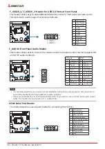
F_PANEL: Front Panel Header
This connector includes Power-on, Reset, HDD LED and Power LED connections. It allows user
to connect the PC case’s front panel switch functions.
Pin Assignment
Function
Pin Assignment
Function
1
HDD LED(+) HDD
LED
2
Power LED (+) Power
LED
3
HDD LED(-)
4
Power LED (-)
5
Ground
Reset
Button
6
Power Button
Power-On
Button
7
Reset Control
8
Ground
9
NC
NC
10 NA
NA
Summary of Contents for H81MHV3 3.0
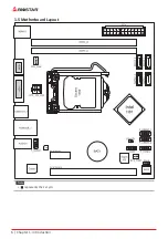
Page 6: ...6 Chapter 1 Introduction 1 5 Motherboard Layout Note represents the 1st pin ...
Page 36: ...6 Глава 1 Введение 1 5 Компоновка материнской платы представляет собой 1 й контакт ...
Page 63: ...챕터 1 들어가는 글 7 H81MHV3 3 0 1 5 마더보드 레이아웃 는 첫번째 핀을 표시합니다 ...
Page 84: ...28 챕터 4 유용한 도움말 이 페이지는 의도적으로 비워 둔 것입니다 ...
Page 90: ...6 第一章 主板介绍 1 5 主板結構圖 標示為針腳1 ...


