


BIH11-AHB User’s Manual
10 | Chapter 2: Hardware installation
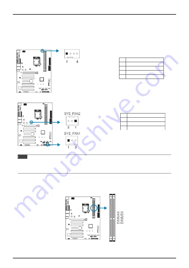
Pin
Assignment
1
GND
2
12V
3
FAN_TACH
2.3
Connect Cooling Fans
These fan headers support cooling-fans built in the computer. The fan cable and connector
may be different according to the fan manufacturer. Connect the fan cable to the connector
while matching the black wire to pin#1.
CPU_FAN1: CPU Fan Header
Pin
Assignment
1
GND
2
FANPVOUT
3
FAN_TACH
4
FANPWMOUT
SYS_FAN1/2: System Fan Header
»
System Fan Headers support 3-pin head connectors. When connecting with wires onto connectors,
please note that the red wire is the positive and should be connected to pin#2, and the black wire is
Ground and should be connected to GND.
2.4
Installing System Memory
DDR4 Modules
Note