10
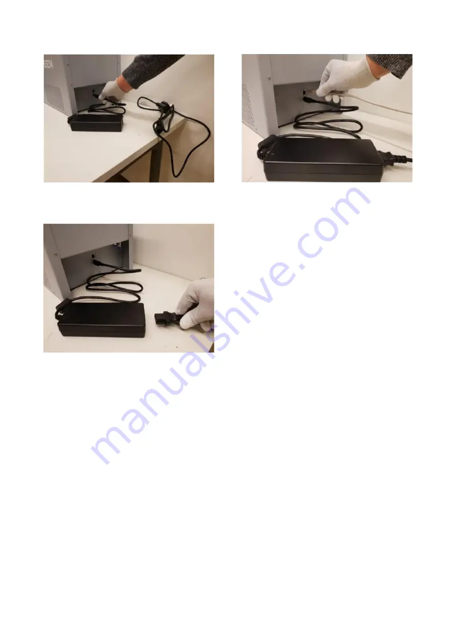
Figure 5-1: How to connect the power cable.
Figure 5-2: How to connect the power adapter.
Note:
Whenever disconnecting the power cable, please
note that the connector is equipped with a cable
strain relief, and must only be detached by
releasing the lock, sliding the connector mantle
backwards.
5.3.2 Ethernet Communication Connection
Connect the RJ45 Ethernet cable between the
Bioscreen C° Pro and local Ethernet network
(directly to computer or via network router based
on local policies).
Figure 5-3: How to connect the Ethernet cable.
Network settings for the Bioscreen C° Pro are
either entered manually via device user interface
(default) or collected automatically from a DHCP
server.
Note:
If you are unsure which to use, contact your local
IT support for help.
Communication between the Bioscreen C° Pro
and the software is done with normal TCP/IP
protocol. Default connection method is a direct
point-to-point connection between the Bioscreen
C° Pro instrument and the computer. This works
well in environments where the computer does
not need access to other local network resources.
It is also possible to connect the Bioscreen C° Pro
to a local network. In this case the IP settings
need to be set to comply with local network
policies. Consult your local IT specialist for
network details prior connecting the Bioscreen C°
Pro to local network.
5.3.3 Manual Setup for Direct Connection
between the Bioscreen C° Pro and the
Computer
By default, Bioscreen C° Pro is set for direct point-
to-point connection with your computer. If you
are using this connection method, you will only
need to configure your computer’s network
settings to comply with Bioscreen C° Pro’s.
Default IP address for Bioscreen C° Pro is
192.168.1.10


