background image

Access


Control


Instruction


Manual


3


Step 1: Install the device and power on the device; 

Step 2: User Registration, Fingerprint Registration, ID / IC Card, Password, Assignment Rights; 

Step 3: user authentication, confirm the registration fingerprint, ID / IC card, the password is available; 

Step 4: View records, through the access control software to download the original records of 

equipment for data analysis. 

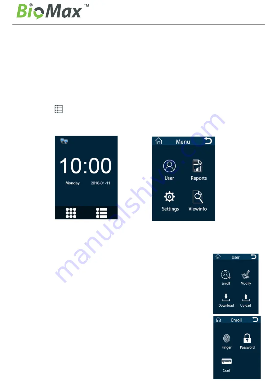
3.2 The initial interface and main menu 

After the device is connected to the power, the first interface shown on the screen is called the initial 

interface; Click “       ”enter the main menu,   

When setting up an administrator, the administrator must identify the fingerprint, ID / IC card or 

password is successful, it can enter the main menu. 

Initial Interface

Main Menu 

3.3 Verification Mode 

In the initial interface, Users through the fingerprint, ID/IC card, password authentication identity, After 
the verification is successful, the original record will be saved on the device, 
Voice prompt "OK!", Then return to the initial interface. 

4. User management

Select "User" to enter the user management interface on main menu.  
User data can be backed up or uploaded to another device of the same series. 

4.1 Add new users 

New employee enter employee number and name, Then register fingerprint, ID 
/ IC card or password. 

4.1.1 Fingerprint registration 

Click “Finger”, According to the hint enter the employee number and name, 
Press the fingerprint capture window three times with the finger you want to 
register, You can complete the fingerprint registration, During verification, press 
the registered finger to identify under the initial interface 

Summary of Contents for N-BM300

Page 1: ...User Manual www biomaxsecurity com N BM300 Fingerprint Time Attendance and Access Control...

Page 2: ...Access Control Instruction Manual 1 Access Control Manual 1 Notice for use 1 1 Access Control wiring diagram Access Control External Power wiring diagram recommendation General Power wiring diagram...

Page 3: ...is the drilling position Figure 1 2 1 2 Find the frame groove position Figure 2 Gently remove the frame use hand Figure 3 2 1 3 That the backing plate bonded to the bottom cover with the device inser...

Page 4: ...n enter the main menu Initial Interface Main Menu 3 3 Verification Mode In the initial interface Users through the fingerprint ID IC card password authentication identity After the verification is suc...

Page 5: ...OK enter Sunday Saturday s time period selection 1 refers to the time period number 1 New registered users default time period 1 that is open all day Note For the definition of time period please refe...

Page 6: ...ndance logs Delete All Log Delete all attendance logs but not delete user information the password is 8282 Delete All Data Delete all registered users and attendance logs please use with caution the p...

Page 7: ...ings the screen as follows For example Allow the door to open at 04 00 11 00 03 00 06 00 11 00 18 00 By analogy you can define multiple time periods as needed Note the system default time1 open all da...

Page 8: ...p the alarm by clicking this item 6 4 7 Tamper Alert Tamper alert has two statuses Yes and No Yes refers to turning on tamper alert function an alarm occurs when the device is removed No refers to the...

Reviews: