background image

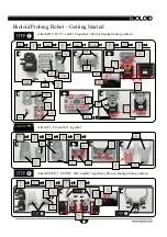
Bioloid Probing Robot – Getting Started

Attach ID5, F2, F3, and F10 together. (Do not misalign horn position.)

Attach F1, F9, and F11 together.

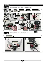
Attach STEP

, STEP

, ID6, and ID7 together. (Do not misalign horn position.)

S1


2

x 4

F3

x 2

BU

x 1

F


2

x 1

W


A

x 1

N


1

x 4

N


1

S12

S


1

WA

BU

S-B

F3

F2

W


A

BU

S-B

S12

S-B

x 1

F10

x 2

S4

x 4

F10

F3

S4

N


1

S


4

S


1

S


1

x 8

N


1

x 8

F1


1

x 2

F


9

x 2

F1

x 2

F


1

F9

F1


1

N1

S


1

W


A

B


U

S-


B

BU

x 2

W


A

x 2

S-


B

x 2

N


1

x 8

W


A

BU

S-


B

N


1

S


1

x 8

3

1

2

3

4

3-


1

2-


1

1

2

3

4

2-


1

1

2

3

F2

F3

F10

x 2

F3

F1


1

F1


1

F1

F9

Summary of Contents for Premium Kit

Page 1: ...obot Assembly manual 1 Bioloid Premium Kit Probing Robot Assembly Manual v1 0 ROBOTIS EXCLUSIVE DISTRIBUTOR RO BOTICA GLOBAL S L C Hercegovina 22 bajos 08006 Barcelona Spain www ro botica com Tel 34 9...

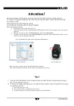
Page 2: ...ress 30 Goal Position click on Center Position Dynamixel Wizard will then align the horn you can visually verify horn alignment afterwards For more information please refer to Dynamixel Management I A...

Page 3: ...ether Do not misalign horn position S1 2 x 4 F3 x 2 BU x 1 F 2 x 1 W A x 1 N 1 x 4 N 1 S12 S 1 WA BU S B F3 F2 W A BU S B S12 S B x 1 F10 x 2 S4 x 4 F10 F3 S4 N 1 S 4 S 1 S 1 x 8 N 1 x 8 F1 1 x 2 F 9...

Page 4: ...7 Connect ID5 with CABLE 10 F3 x 1 F54 x 1 IR SENSOR x 1 RIVET x 4 5P CABLE 15 x 1 N1 RIVET RIVET 5P CABLE 15 S1 S1 F3 IR SENSOR F54 DMS x 1 DMS RIVET 5P CABLE 15 S1 x 8 N 1 x 4 CABLE 10 x 3 CABLE 10...

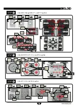
Page 5: ...and F51 together Attach F3 F10 and F60 together N1 F3 N1 S1 F3 x 6 S1 x 24 N1 x 36 F55 x 8 F55 F1 3 x 4 S 1 x 8 F1 4 x 4 F1 4 F1 3 S 2 F5 1 x 1 S 2 x 16 S1 F5 1 F3 x 1 S5 x 4 F10 x 2 F60 x 1 N1 x 4 F...

Page 6: ...LE 20 Attach STEP F52 and CM 510 together Connect ID3 to CM 510 with CABLE 20 Connect IR SENSOR to Port 2 of CM 510 with 5P CABLE 15 Connect DMS to Port 1 of CM 510 with CABLE DMS F52 x 1 CM 510 x 1 S...

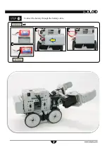
Page 7: ...7 Connect the battery through the battery cable BATTERY BATTERY x 1 1 2 3...

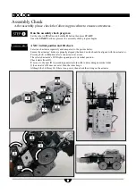
Page 8: ...y and compare it to the picture below Ensure the actuators horns are properly aligned the horn s notch should be aligned with the actuator s Pressing the U or D button selects one actuator at a time T...

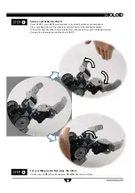
Page 9: ...r and behavior check From STEP press R The robot returns to its initial position as pictured above Place your hand close to the sensors as pictured below Robot behavior begins If the robot does not be...

Reviews: